Uploaded on
25 Jan 2023
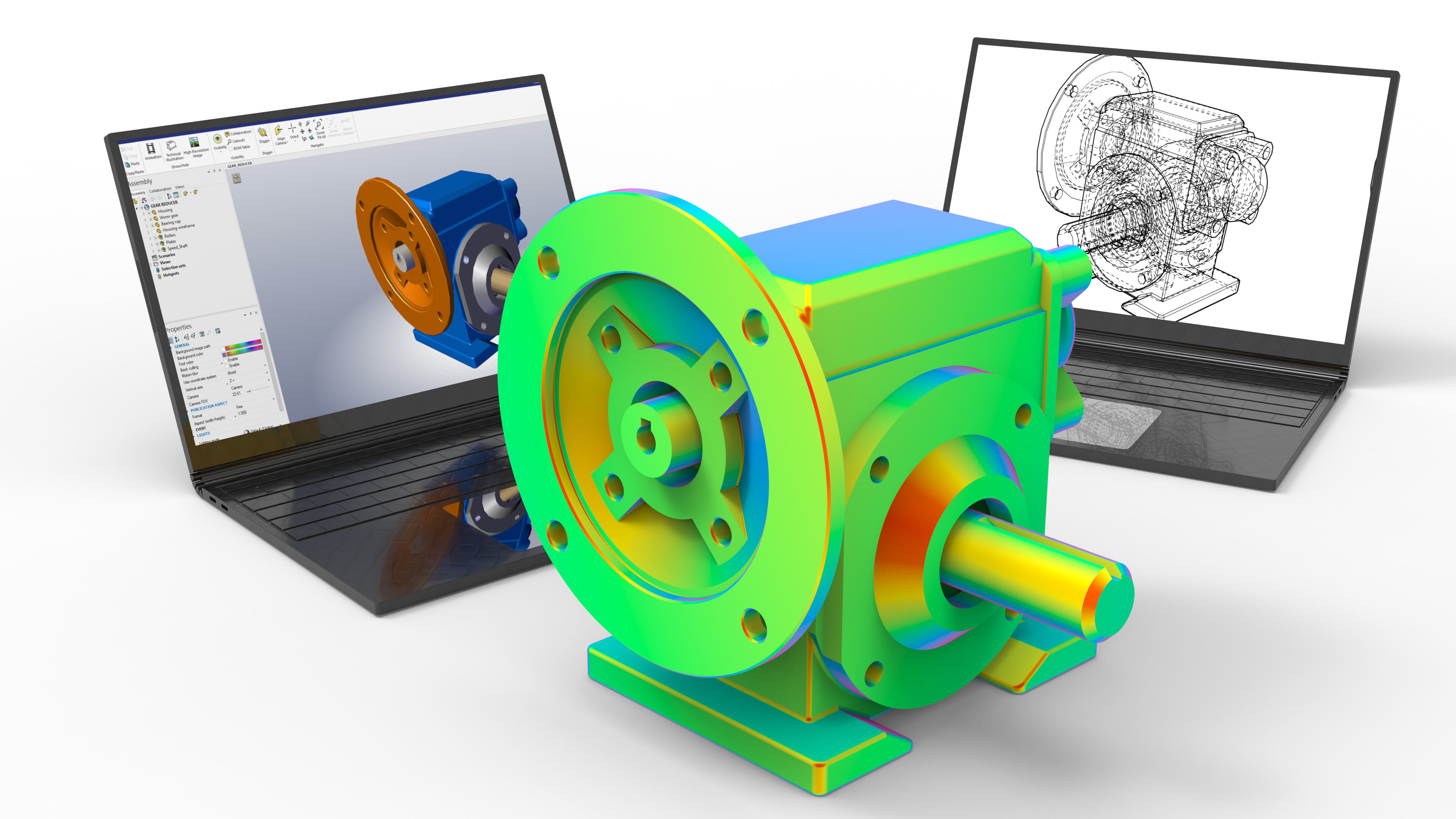
Structured and Unstructured Grids in FEA

Skill-Lync
Structured grids are identified by regular connectivity. The possible element choices are quadrilateral in 2D and hexahedral in 3D. This model is highly space efficient since the neighborhood relationships are defined by storage arrangement. Some other advantages of structured grid over an unstructured one are better convergence and higher resolution.
Meshes with implicit connection have a structure that makes it simple to recognize their components, and nodes are known as structured meshes. Orthogonal quadrilateral (2D) or hexahedral (3D) pieces are frequently seen in organized meshes.
Programmers can enumerate the nodes in structured meshes in such a way that any nearby elements or nodes can be called upon without being aware of any connectivity details. Since the size of each element is constant from element to element, accessing coordinates is similarly simple.
_1674658479.png)
Unstructured Grids
An unstructured grid is identified by irregular connectivity. It cannot easily be expressed as a two-dimensional or three-dimensional array in computer memory. This allows for any possible element that a solver can use. Compared to structured meshes, this model can be highly space inefficient since it calls for explicit storage of neighborhood relationships. These grids typically employ triangles in 2D and tetrahedral in 3D.
Unstructured meshes are general connectivity (GCON) meshes whose structure is arbitrary, necessitating the definition and storage of element connectivity. Non-orthogonal GCON element types include tetrahedra and triangles (2D) (3D).
Programmers must map additional data to each node in unstructured meshes, such as adjacency lists and coordinate lists.
_1674658616.png)
Hybrid Grids
A hybrid grid contains a mixture of structured portions and unstructured portions. It integrates structured meshes and unstructured meshes in an efficient manner. Those parts of the geometry that are regular can have structured grids, and those that are complex can have unstructured grids. These grids can be non-conformal, meaning grid lines don’t need to match at block boundaries.
_1674658649.png)
Deciding The Type of Grid To Choose
There are two questions to consider while choosing the right grid:
- Do you have a complicated geometry where the shape of the geometry is essential to the design?
- Do specific areas of your model need a mesh with a better resolution?
The best choice of mesh depends on a number of factors, including ease of generation, memory needs, computation time, numerical accuracy, and suitability for the application. The ability to adapt to any desired shape with localised resolutions is an unstructured mesh's primary advantage, so if the answer to either of these questions is yes, you might wish to use one. If you don't need any of these features, an unstructured mesh won't be necessary, and you can reduce computation time and memory requirements by using a structured grid.
Advantages and disadvantages of Structured & Unstructured Grids
Advantages of structured grids:
- Efficient with memory
- Quick to solve
Advantages of unstructured grids:
- Complex geometries mesh more easily
- Undefined positions
Disadvantages of structured grids:
Geometries with angles and curves are approximations.
Disadvantages of unstructured grids:
- More memory is needed
- Less quickly solved
Author

Navin Baskar
Author
Skill-Lync
Subscribe to Our Free Newsletter

Continue Reading
Related Blogs
Learn how to render a shock-tube-simulation and how to work on similar projects after enrolling into anyone of Skill-Lync's CAE courses.
10 May 2020
In this blog, read how to design the frontal BIW enclosure of a car (Bonnet) and learn how Skill-Lync Master's Program in Automotive Design using CATIA V5 will help you get employed as a design engineer.
10 May 2020
Tetrahedral is a four- nodded solid element that can be generated through the tria element by creating a volume and also through the existing volume of the geometry. These elements are used where the geometry has high thickness and complexity. The image attached below is a representation of a Tetra element. The Tetra element will have 4 triangular faces with four nodes joining them together
02 Aug 2022
A connector is a mechanism that specifies how an object (vertex, edge, or face) is connected to another object or the ground. By often simulating the desired behaviour without having to build the precise shape or specify contact circumstances, connectors make modeling simpler.
03 Aug 2022
One of the most crucial processes in carrying out an accurate simulation using FEA is meshing. A mesh is composed of elements that have nodes—coordinate positions in space that might change depending on the element type—that symbolise the geometry's shape.
04 Aug 2022
Author
Skill-Lync
Subscribe to Our Free Newsletter
Continue Reading
Related Blogs
Learn how to render a shock-tube-simulation and how to work on similar projects after enrolling into anyone of Skill-Lync's CAE courses.
10 May 2020
In this blog, read how to design the frontal BIW enclosure of a car (Bonnet) and learn how Skill-Lync Master's Program in Automotive Design using CATIA V5 will help you get employed as a design engineer.
10 May 2020
Tetrahedral is a four- nodded solid element that can be generated through the tria element by creating a volume and also through the existing volume of the geometry. These elements are used where the geometry has high thickness and complexity. The image attached below is a representation of a Tetra element. The Tetra element will have 4 triangular faces with four nodes joining them together
02 Aug 2022
A connector is a mechanism that specifies how an object (vertex, edge, or face) is connected to another object or the ground. By often simulating the desired behaviour without having to build the precise shape or specify contact circumstances, connectors make modeling simpler.
03 Aug 2022
One of the most crucial processes in carrying out an accurate simulation using FEA is meshing. A mesh is composed of elements that have nodes—coordinate positions in space that might change depending on the element type—that symbolise the geometry's shape.
04 Aug 2022
Related Courses