Menu


Modified on
Co-ordinate vs Position Tolerance
Skill-Lync
Are you thinking that Basic Dimension (coordinate tolerance) is sufficient to determine the position ?.If we apply position tolerance what are the changes ? Let's find out.
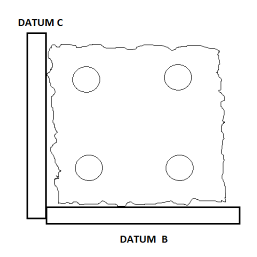
Consider a square block with four holes, as shown in the figure below.

Let's consider the basic dimension.
We can form a square tolerance zone of length 0.1 and breath of 0.1.
The part will be approved only if the center of the holes lies within the square tolerance zone. If the part measurement is outside the square tolerance zone, either the part is rejected or submit a deviation to the designer to see if this is functionally acceptable. The part created out of tolerance will cost time and money.
The first step is to determine the function of the part and what is the goal when locating these holes.?Assume that the part is fixed with a bolt to a slot with the dimension. We want to make sure that the center of the hole is not too far from the target. Bolts are round, and the holes are round. Why should the tolerance zone be limited to squares?
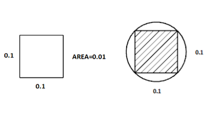
If we use position tolerance with a diameter symbol, we will get a 56% larger tolerance zone by providing the same function.
Repeatable measurement using coordinate tolerance.
To find out the center of the hole, we can use CMM (Coordinate Measuring Machine) for accurate measurement. We would need to touch off the left surface and measure the hole to determine the center of the part. Then we will repeat the procedure for the y dimension from the bottom. Next, we will repeat this for all four holes to see whether the center location matches the tolerance.

We can see that the left edge is imperfect. This will lead to a wide range of measurements that will not truly reflect how the part functions. By this method, we will not get repeatable measurements that mimic the function.
Repeatable measurement using position tolerance?
The position allows you to pinpoint a functional location for your hole center in space using datum. Then specify a tolerance around that true position.
We Will use a datum feature simulator to simulate part datums and control the part with functional intent.
One of the strengths of GD&T is creating repeatable measurements that mimic the function of the part. By applying the position tolerance, we save time and money. Now we can ensure that the bolts will always assemble and function on the part.
Author

Navin Baskar
Author
Skill-Lync
Subscribe to Our Free Newsletter

Continue Reading
Related Blogs
Learn how to render a shock-tube-simulation and how to work on similar projects after enrolling into anyone of Skill-Lync's CAE courses.
09 May 2020
In this blog, read how to design the frontal BIW enclosure of a car (Bonnet) and learn how Skill-Lync Master's Program in Automotive Design using CATIA V5 will help you get employed as a design engineer.
09 May 2020
Tetrahedral is a four- nodded solid element that can be generated through the tria element by creating a volume and also through the existing volume of the geometry. These elements are used where the geometry has high thickness and complexity. The image attached below is a representation of a Tetra element. The Tetra element will have 4 triangular faces with four nodes joining them together
01 Aug 2022
A connector is a mechanism that specifies how an object (vertex, edge, or face) is connected to another object or the ground. By often simulating the desired behaviour without having to build the precise shape or specify contact circumstances, connectors make modeling simpler.
02 Aug 2022
One of the most crucial processes in carrying out an accurate simulation using FEA is meshing. A mesh is composed of elements that have nodes—coordinate positions in space that might change depending on the element type—that symbolise the geometry's shape.
03 Aug 2022
Author
Skill-Lync
Subscribe to Our Free Newsletter
Continue Reading
Related Blogs
Learn how to render a shock-tube-simulation and how to work on similar projects after enrolling into anyone of Skill-Lync's CAE courses.
09 May 2020
In this blog, read how to design the frontal BIW enclosure of a car (Bonnet) and learn how Skill-Lync Master's Program in Automotive Design using CATIA V5 will help you get employed as a design engineer.
09 May 2020
Tetrahedral is a four- nodded solid element that can be generated through the tria element by creating a volume and also through the existing volume of the geometry. These elements are used where the geometry has high thickness and complexity. The image attached below is a representation of a Tetra element. The Tetra element will have 4 triangular faces with four nodes joining them together
01 Aug 2022
A connector is a mechanism that specifies how an object (vertex, edge, or face) is connected to another object or the ground. By often simulating the desired behaviour without having to build the precise shape or specify contact circumstances, connectors make modeling simpler.
02 Aug 2022
One of the most crucial processes in carrying out an accurate simulation using FEA is meshing. A mesh is composed of elements that have nodes—coordinate positions in space that might change depending on the element type—that symbolise the geometry's shape.
03 Aug 2022
Related Courses


