Modified on
How to Save Your SolidWorks Models in a Parasolid Format

Skill-Lync
Working on Parasolid files and saving management for it in Solidworks for an assembly can be confusing for many professionals. This article will help you understand:
- What are the Parasolid files?
- Creation of Parasolid parts from a part file and saving them
- Importing Parasolid part file in Solidworks
- Saving an imported Parasolid part file as a SolidWorks part file
What are the Parasolid files?
Parasolid files are 3D geometric modeling components that are selected by leading vendors and many end-user organizations. It can be utilized for many different applications and can be operated in CAD software including Solidworks. Many CAD software uses Parasolid files for interoperability such that the 3D model can be accessed. They are used to capture detail-rich information of highly complex 3D models. It is used in Computer-aided design (CAD), Computer-aided manufacturing (CAM), Computer-aided engineering (CAE), Product visualization, and CAD data exchange packages.
The Parasolid files can be saved in .x_t and .x_b extensions. The .x_t extension files are usually used in Solidworks as it contains more information about the 3D model. But if you run into any error while working with .x_t files, we can also work on the .x_b file type. It helps you create a separate solid model within a part file into a separate file.
How to create a Parasolid file from a 3D CAD model in Solidworks?
Currently, there are two solid bodies present in the cavity block as shown below:

Right-click on the body to be separated, and select and select insert in new part:

After clicking on insert in the new part, the following window appears, and click on the green arrow marked below:

After clicking on okay, a separate window with a part will appear with another window for saving the part file in the folder.

We will give a name to the solid model, and select the address for the file. Whereas we will select the save as type extensions as Parasolid x_t:

The file will be saved in the folder with the given name.

This way, a Parasolid part file is created.
How to create a Solidworks part file from the Parasolid part file?
To convert a Parasolid file into a Solidworks part file, we first need an empty part file of the Solidworks, we will create that in the assembly and give it the name “slider_01,” and we will edit this file:

After the part file to be edited is selected. We will click on the insert tab → features → imported:

After clicking on imported a window will appear from where you can select the previously saved Parasolid file:
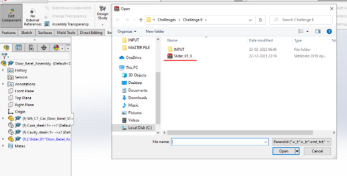
As it can be observed the Parasolid file is imported in the part file within an assembly:

Saving an imported Parasolid part file as a SolidWorks part file:
You can select the file in edit mode. Go to the file → save as:

And the window for the path for the folder where the file needs to be saved appears. You can give an appropriate name to the part file:

It will be saved as a SolidWorks part file in the required folder:

This way you can create a Parasolid part file and convert it to the Solidworks part file.
Author

Navin Baskar
Author
Skill-Lync
Subscribe to Our Free Newsletter

Continue Reading
Related Blogs
Learn how to render a shock-tube-simulation and how to work on similar projects after enrolling into anyone of Skill-Lync's CAE courses.
09 May 2020
In this blog, read how to design the frontal BIW enclosure of a car (Bonnet) and learn how Skill-Lync Master's Program in Automotive Design using CATIA V5 will help you get employed as a design engineer.
09 May 2020
Tetrahedral is a four- nodded solid element that can be generated through the tria element by creating a volume and also through the existing volume of the geometry. These elements are used where the geometry has high thickness and complexity. The image attached below is a representation of a Tetra element. The Tetra element will have 4 triangular faces with four nodes joining them together
01 Aug 2022
A connector is a mechanism that specifies how an object (vertex, edge, or face) is connected to another object or the ground. By often simulating the desired behaviour without having to build the precise shape or specify contact circumstances, connectors make modeling simpler.
02 Aug 2022
One of the most crucial processes in carrying out an accurate simulation using FEA is meshing. A mesh is composed of elements that have nodes—coordinate positions in space that might change depending on the element type—that symbolise the geometry's shape.
03 Aug 2022
Author
Skill-Lync
Subscribe to Our Free Newsletter
Continue Reading
Related Blogs
Learn how to render a shock-tube-simulation and how to work on similar projects after enrolling into anyone of Skill-Lync's CAE courses.
09 May 2020
In this blog, read how to design the frontal BIW enclosure of a car (Bonnet) and learn how Skill-Lync Master's Program in Automotive Design using CATIA V5 will help you get employed as a design engineer.
09 May 2020
Tetrahedral is a four- nodded solid element that can be generated through the tria element by creating a volume and also through the existing volume of the geometry. These elements are used where the geometry has high thickness and complexity. The image attached below is a representation of a Tetra element. The Tetra element will have 4 triangular faces with four nodes joining them together
01 Aug 2022
A connector is a mechanism that specifies how an object (vertex, edge, or face) is connected to another object or the ground. By often simulating the desired behaviour without having to build the precise shape or specify contact circumstances, connectors make modeling simpler.
02 Aug 2022
One of the most crucial processes in carrying out an accurate simulation using FEA is meshing. A mesh is composed of elements that have nodes—coordinate positions in space that might change depending on the element type—that symbolise the geometry's shape.
03 Aug 2022
Related Courses