


Modified on
Turbomachinery: How These Machines Are Making the World a Cleaner Place

Skill-Lync
Turbomachinery refers to a class of machines that transfer energy between a rotor and a fluid. These machines are primarily used for the conversion of energy between mechanical work and fluid flow, typically involving the compression, expansion, or transfer of fluids such as gases or liquids. Turbomachinery plays a crucial role in various industries, including power generation, aviation, oil and gas, chemical processing, and transportation. Turbomachinery can be broadly categorized into two main types:
- Turbines: Turbines extract energy from a fluid and convert it into useful work
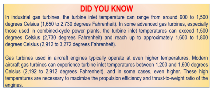
- Turbines are commonly found in power generation applications, where they extract energy from hot gases produced by the combustion of fossil fuels or other heat sources.
- This energy is then converted into mechanical work, typically used to drive generators and produce electricity. Turbines are also utilized in aviation engines, where they extract energy from combustion gases to propel aircraft.
- Compressors: Compressors do the opposite by adding energy to the fluid and raising its pressure
- Compressors, on the other hand, are used to increase the pressure and density of a fluid, such as air or gas.
- They find application in processes like gas transportation, refrigeration, air conditioning, and industrial processes where pressurized fluid flow is required.
- Compressors can be classified based on their operating principle, such as centrifugal, axial, or reciprocating compressors, each suited for specific applications.
- Both turbines and compressors consist of a rotor and a stationary component known as a stator, which is designed to transfer energy to or from the fluid. efficiently
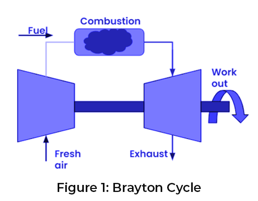
Perhaps the best way to describe the cycle of dependency between turbines and compressors would be to use the Brayton cycle.
CFD for Turbomachinery
Computational Fluid Dynamics (CFD) plays a crucial role in the design, analysis, and optimization of turbomachinery. CFD is a numerical simulation technique used to solve the governing equations of fluid flow and heat transfer. In the context of turbomachinery, CFD allows engineers to study and predict the behavior of fluids and their interaction with rotor and stator components.
Here are some specific roles that CFD plays in turbomachinery:
-
Performance Prediction:
- CFD simulations help in predicting the performance characteristics of turbomachinery components such as turbines and compressors
- By simulating the fluid flow and thermodynamics within these machines, engineers can estimate critical parameters like pressure, temperature, velocity, and efficiency
- This information aids in understanding the behavior of the turbomachinery and optimizing its design
-
Flow Visualization:
- CFD enables engineers to visualize and analyze the complex flow patterns within turbomachinery
- By examining variables like velocity vectors, pressure contours, and streamline patterns, they can identify regions of flow separation, recirculation, and potential performance issues
- This insight guides the design process to improve efficiency and reduce losses
-
Aerodynamic
- Design Optimization: CFD facilitates the optimization of turbomachinery blade geometries
- Through parametric studies and optimization algorithms, engineers can explore various design options and evaluate their impact on performance
- CFD simulations aid in assessing the effect of changes in blade shape, angles, and other parameters, enabling the development of more efficient and reliable turbomachinery
-
Cavitation and Two-Phase Flow Analysis:
- In certain turbomachinery applications, such as pumps and propellers, the presence of cavitation (formation of vapor bubbles) and two-phase flow can significantly affect performance and lead to damage
- CFD simulations help in studying these phenomena, identifying regions of cavitation, and predicting their impact on performance and structural integrity
-
Off-Design Performance Analysis:
- Turbomachinery often operates under off-design conditions, where flow rates, pressures, and other parameters deviate from design values
- CFD allows engineers to analyze and understand the performance of turbomachinery under different operating conditions, providing insights into efficiency, stability, and potential issues like stall or surge
-
Noise and Vibrations Analysis:
- CFD can also aid in the analysis and prediction of noise and vibrations generated by turbomachinery
- By simulating the flow-induced noise and studying its sources, engineers can optimize the design to minimize noise levels and address potential structural vibration issues
Velocity Triangle
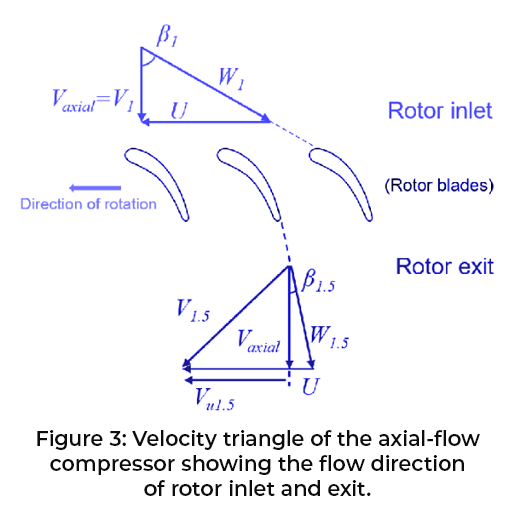
One simplification one can make when analyzing turbomachines is to use the concept of the Velocity Triangle. The velocity triangle, also known as the velocity diagram or triangle of velocities, is a graphical representation used to analyze the flow of fluid through a turbomachine, such as a turbine or compressor. It provides a geometric representation of the velocities and angles of the fluid at different sections within the turbomachinery. It helps engineers optimize blade shapes, determine the flow angles for efficient energy transfer, and assess the performance of the turbomachinery under different operating conditions.
The velocity triangle is typically drawn at the inlet and outlet sections of a rotor or stator blade row in a turbomachine. It consists of three vectors: the absolute velocity (V), the relative velocity (W), and the blade velocity (U). These vectors are drawn to scale and are typically represented as arrows.
Here are the key components of the velocity triangle:
-
Absolute Velocity (V):
- The absolute velocity represents the velocity of the fluid relative to a fixed reference frame
- It is the vector sum of the fluid velocity (V) and the velocity of the reference frame
- The absolute velocity is typically shown as an arrow pointing in the direction of fluid flow
-
Relative Velocity (W):
- The relative velocity represents the velocity of the fluid relative to the moving blades of the turbomachinery
- It is obtained by subtracting the velocity of the blades (U) from the absolute velocity (V)
- The relative velocity is typically shown as an arrow pointing in the opposite direction of the blade velocity
-
Blade Velocity (U):
- The blade velocity represents the velocity of the moving blades in the reference frame of the turbomachine
- It is the vector sum of the rotational speed of the blades and the tangential velocity of the blade tip
- The blade velocity is typically shown as an arrow perpendicular to the blade surface
The velocity triangle allows engineers to analyze and understand the fluid flow characteristics within the turbomachinery. By examining the magnitudes and directions of the velocity vectors, as well as the associated angles, engineers can determine important parameters such as flow angles, blade angles, and relative velocities.
Key Outputs:
In a CFD study for turbomachinery applications, there are several key output results that engineers typically expect. These results provide valuable insights into the behavior and performance of the turbomachinery under consideration.
Some of the key output results include:
-
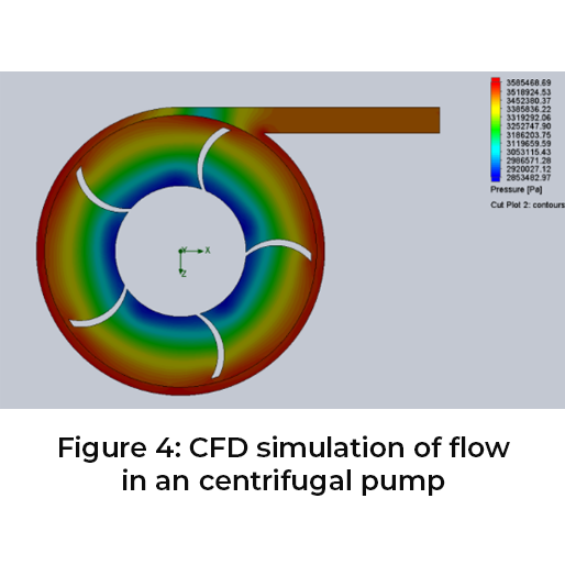
Pressure Distribution:
- CFD simulations provide information on the pressure distribution throughout the turbomachinery components
- This includes pressure contours, gradients, and variations at different sections, helping engineers identify areas of high or low pressure, flow separation, and potential performance issues
-
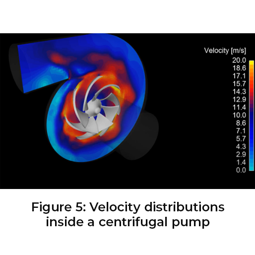
Velocity Distribution:
- CFD simulations yield velocity profiles and vectors, illustrating the distribution and magnitude of fluid velocities within the turbomachinery
- These results help engineers understand the flow patterns, identify regions of high or low velocity, and assess the efficiency of energy transfer between the fluid and the blades
-
Flow Visualization:
- CFD allows for visualizing the flow behavior within the turbomachinery
- By examining flow streamlines, velocity vectors, and other visualization techniques, engineers can gain insights into the complex fluid flow patterns, identify areas of recirculation or flow separation, and assess the overall flow characteristics
-
Efficiency and Performance Parameters:
- CFD simulations provide information on various performance parameters of the turbomachinery, including efficiency, power output, pressure ratio, and mass flow rate
- These results help in evaluating the performance of the turbomachinery design, optimizing its efficiency, and comparing different design configurations
-
Blade Loading and Forces:
- CFD simulations can estimate the forces and loading on the blades of turbomachinery
- This information helps engineers assess structural integrity, evaluate blade performance, and optimize the design to minimize stresses, vibrations, and potential failures
-
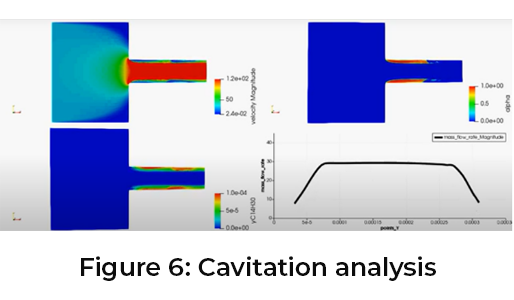
Cavitation and Two-Phase Flow Analysis:
- For turbomachinery applications involving liquids, such as pumps or propellers, CFD can predict the occurrence of cavitation and study two-phase flow phenomena
- Results can include the prediction of cavitation regions, vapor fraction distributions, and the impact of cavitation on performance and durability.
Is Turbomachinery Complex?
Turbomachinery analysis in CFD (Computational Fluid Dynamics) can be complex due to several factors. Here are some reasons why turbomachinery analysis in CFD can be challenging:
-
Three-Dimensional Flow:
- Turbomachinery typically involves complex three-dimensional flows, including the interaction between rotating and stationary components
- Modeling and analyzing such flows require the use of advanced computational techniques and specialized turbulence models to accurately capture the flow physics
-
Rotating Frame of Reference:
- Turbomachinery operates in a rotating frame of reference, which adds complexity to the analysisHeat Transfer Analysis:
- CFD simulations provide insights into the heat transfer characteristics within turbomachinery components
- This includes heat transfer coefficients, temperature distributions, and thermal gradients
- Such results aid in assessing cooling requirements, optimizing blade designs for temperature management, and preventing overheating or thermal damage
-
Losses and Efficiency Breakdown:
- CFD can provide detailed information about various losses in turbomachinery, including aerodynamic losses, boundary layer losses, and losses due to secondary flows
- These results allow engineers to analyze the sources of inefficiency, identify areas for improvement, and optimize the design to enhance overall performance
- The transformation of equations and the handling of rotating domains require careful treatment to ensure accurate predictions of flow behavior and interactions with the blades
-
Boundary Layer Modeling:
- The presence of boundary layers, particularly near the blade surfaces, is crucial for accurate turbomachinery analysis
- Proper modeling of the boundary layer, including transition and separation, is necessary to capture the effects of viscous flow, turbulence, and heat transfer accurately
-
Turbulence Modeling:
- Turbulence is an inherent feature of turbomachinery flows, and its modeling presents challenges in CFD
- Selecting appropriate turbulence models that can capture the complex flow phenomena, such as separation, secondary flows, and wakes, is crucial for accurate predictions and reliable results
-
Meshing Challenges:
- Generating suitable computational meshes for turbomachinery analysis can be demanding
- It requires creating high-quality meshes with sufficient resolution in regions of interest, such as blade surfaces, boundary layers, and flow separations
- Meshing complexity increases with the inclusion of blade-to-blade domains and the need to capture flow interactions between rotor and stator rows
-
Convergence and Computational Resources:
- Turbomachinery simulations often require significant computational resources due to the complex flow physics and the need for fine grids in critical regions
- Achieving convergence can be challenging, and the simulations may involve long computational times
-
Design Optimization:
- CFD is frequently used for design optimization in turbomachinery
- This involves exploring a large design space and optimizing multiple parameters, which can be computationally intensive and require sophisticated optimization algorithms

Despite these challenges, CFD remains an essential tool for turbomachinery analysis, offering valuable insights into flow behavior, performance characteristics, and design optimization. Advancements in computational methods, turbulence modeling, meshing techniques, and high-performance computing continue to enhance the accuracy and efficiency of turbomachinery analysis in CFD.
Author

Navin Baskar
Author
Skill-Lync
Subscribe to Our Free Newsletter

Continue Reading
Related Blogs
Learn how to render a shock-tube-simulation and how to work on similar projects after enrolling into anyone of Skill-Lync's CAE courses.
09 May 2020
In this blog, read how to design the frontal BIW enclosure of a car (Bonnet) and learn how Skill-Lync Master's Program in Automotive Design using CATIA V5 will help you get employed as a design engineer.
09 May 2020
Tetrahedral is a four- nodded solid element that can be generated through the tria element by creating a volume and also through the existing volume of the geometry. These elements are used where the geometry has high thickness and complexity. The image attached below is a representation of a Tetra element. The Tetra element will have 4 triangular faces with four nodes joining them together
01 Aug 2022
A connector is a mechanism that specifies how an object (vertex, edge, or face) is connected to another object or the ground. By often simulating the desired behaviour without having to build the precise shape or specify contact circumstances, connectors make modeling simpler.
02 Aug 2022
One of the most crucial processes in carrying out an accurate simulation using FEA is meshing. A mesh is composed of elements that have nodes—coordinate positions in space that might change depending on the element type—that symbolise the geometry's shape.
03 Aug 2022
Author
Skill-Lync
Subscribe to Our Free Newsletter
Continue Reading
Related Blogs
Learn how to render a shock-tube-simulation and how to work on similar projects after enrolling into anyone of Skill-Lync's CAE courses.
09 May 2020
In this blog, read how to design the frontal BIW enclosure of a car (Bonnet) and learn how Skill-Lync Master's Program in Automotive Design using CATIA V5 will help you get employed as a design engineer.
09 May 2020
Tetrahedral is a four- nodded solid element that can be generated through the tria element by creating a volume and also through the existing volume of the geometry. These elements are used where the geometry has high thickness and complexity. The image attached below is a representation of a Tetra element. The Tetra element will have 4 triangular faces with four nodes joining them together
01 Aug 2022
A connector is a mechanism that specifies how an object (vertex, edge, or face) is connected to another object or the ground. By often simulating the desired behaviour without having to build the precise shape or specify contact circumstances, connectors make modeling simpler.
02 Aug 2022
One of the most crucial processes in carrying out an accurate simulation using FEA is meshing. A mesh is composed of elements that have nodes—coordinate positions in space that might change depending on the element type—that symbolise the geometry's shape.
03 Aug 2022
Related Courses


