Modified on
How to Avoid Cut Extrude Disasters in Your Superstructures
Skill-Lync
ISSUE= Cut Extrude Issue In Superstructures.

Reason= This is happening because of any one of the following reasons,
- The sketch has some issues because of the converted entity. (or)
- Translate surface checkbox under the direction-1 below reverse offset may not be selected.
Solution=1
- First we will edit the sketch because it may have some issues due to the converted entity.
- After opening the respected sketch, the edge which I have marked in the below picture is creating some issues, i.E. Causing the cut to extrude with some rebuild errors.
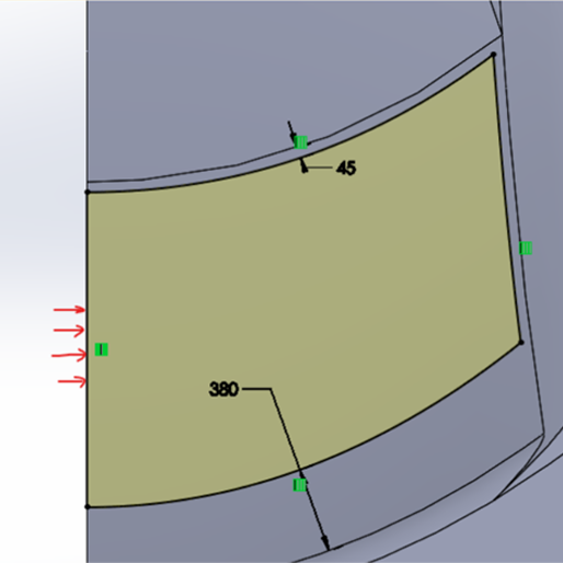
Delete the edge and extend the offset, as shown in the picture below.

Now we are going to use the converted entity feature on the edge, which we have selected to create a closed sketch and make it usable.

Now use the trim option and trim off the extra portions. To get a proper sketch without any extensions.

In most cases, the cut extrudes will work after doing the modification. If it is not working means you can go for the second solution.
Solution=2
- After creating the sketch, we will perform the cut extrude inside the cut extrude. We need to enable some options.
- Under the cut extrude, we need to make sure that reverse offset and translate surface checkboxes are turned on.


Author

Navin Baskar
Author
Skill-Lync
Subscribe to Our Free Newsletter

Continue Reading
Related Blogs
Learn how to render a shock-tube-simulation and how to work on similar projects after enrolling into anyone of Skill-Lync's CAE courses.
09 May 2020
In this blog, read how to design the frontal BIW enclosure of a car (Bonnet) and learn how Skill-Lync Master's Program in Automotive Design using CATIA V5 will help you get employed as a design engineer.
09 May 2020
Tetrahedral is a four- nodded solid element that can be generated through the tria element by creating a volume and also through the existing volume of the geometry. These elements are used where the geometry has high thickness and complexity. The image attached below is a representation of a Tetra element. The Tetra element will have 4 triangular faces with four nodes joining them together
01 Aug 2022
A connector is a mechanism that specifies how an object (vertex, edge, or face) is connected to another object or the ground. By often simulating the desired behaviour without having to build the precise shape or specify contact circumstances, connectors make modeling simpler.
02 Aug 2022
One of the most crucial processes in carrying out an accurate simulation using FEA is meshing. A mesh is composed of elements that have nodes—coordinate positions in space that might change depending on the element type—that symbolise the geometry's shape.
03 Aug 2022
Author
Skill-Lync
Subscribe to Our Free Newsletter
Continue Reading
Related Blogs
Learn how to render a shock-tube-simulation and how to work on similar projects after enrolling into anyone of Skill-Lync's CAE courses.
09 May 2020
In this blog, read how to design the frontal BIW enclosure of a car (Bonnet) and learn how Skill-Lync Master's Program in Automotive Design using CATIA V5 will help you get employed as a design engineer.
09 May 2020
Tetrahedral is a four- nodded solid element that can be generated through the tria element by creating a volume and also through the existing volume of the geometry. These elements are used where the geometry has high thickness and complexity. The image attached below is a representation of a Tetra element. The Tetra element will have 4 triangular faces with four nodes joining them together
01 Aug 2022
A connector is a mechanism that specifies how an object (vertex, edge, or face) is connected to another object or the ground. By often simulating the desired behaviour without having to build the precise shape or specify contact circumstances, connectors make modeling simpler.
02 Aug 2022
One of the most crucial processes in carrying out an accurate simulation using FEA is meshing. A mesh is composed of elements that have nodes—coordinate positions in space that might change depending on the element type—that symbolise the geometry's shape.
03 Aug 2022
Related Courses