


Courses by Software
Courses by Semester
Courses by Domain
Tool-focused Courses
Machine learning
POPULAR COURSES
Success Stories

Creating a Floor plan, Footing detail and Isometric view using AutoCad
AIM - Creating a Floor plan, Footing detail and Isometric view using AutoCad. Q1. Procedure - Type Rec or Rectangle in the command line and press Enter. Specify the first corner of the rectangle. Enter D for Dimensions. Enter the length: .90 Enter the width: .25 Specify the other corner. Type L in the command line…
Mohit Takhalate
updated on 05 Jul 2021


AIM - Creating a Floor plan, Footing detail and Isometric view using AutoCad.
Q1.

Procedure -
Type Rec or Rectangle in the command line and press Enter.
Specify the first corner of the rectangle.
Enter D for Dimensions.
Enter the length: .90
Enter the width: .25
Specify the other corner.

Type L in the command line and press Enter.
Specify the start point a.
Specify next point: @.20, 0
Specify next point:@0, .40
Specify next point:@.05,0
Specify next point:@0, .40
Specify next point:@.05, 0
Specify next point:@0, .60
Specify next point:@.30, 0
Specify next point:@0, -.60
Specify next point:@.05, 0
Specify next point:@0, -.40
Specify next point:@.05, 0
Specify next point:@ 0,-.40

Type L in the command line and press Enter.
Specify the start point b.
Specify next point: @0, .05
Specify next point:@.30, 0
Specify next point:@0,-.05

Type L in the command line and press Enter.
Specify the start point c.
Specify next point: @0, 1
Specify next point:@.30, 0
Specify next point:@0,-1

Type L in the command line and press Enter.
Specify the start point d.
Specify next point: @-.30, 0
Specify next point:@-.05, 0
Specify next point: @-1.15, 0
Specify next point:@0, -.15
Specify next point:@1.15, 0

Type L in the command line and press Enter.
Specify the start point e.
Specify next point: @.30, 0
Specify next point:@0, .15
Specify next point: @.30, 0
Specify next point:@0, .15
Specify next point: @.30, 0
Specify next point:@0, .15
Specify next point: @.30, 0

Type L in the command line and press Enter.
Specify the start point f.
Specify next point: @1, 0
Specify next point:@0, -.60
Specify next point: @-.95, 0

Type DLI or DIMLINEAR on the command line and press Enter.
Give the dimensions as per the drawing.

Result - The C.S of Load bearing wall over spread footing is completed.
Q2.

Procedure -
Type Rec or Rectangle in the command line and press Enter.
Specify the first corner of the rectangle.
Enter D for Dimensions.
Enter the length: 1
Enter the width: .40
Specify the other corner.

Type CHA or CHAMFER in the command line and press enter
Enter D for Distance
Specify first chamfer distance:.25
Specify second chamfer distance:.38
Select the first line ab and second line as bc
Repeat the same step on opposite side on line cd and bc

Delete line ef
Type L in the command line and press Enter.
Specify the start point e.
Specify next point:@0, 1.60
Specify next point:@.24, 0
Specify next point:@0, -1.60

Type L in the command line and press Enter.
Specify the start point g.
Specify next point:@.04, 0
Specify next point:@0, -1.96
Specify next point:@-.38,0
Specify next point:@0,.04

Type L in the command line and press Enter.
Specify the start point h.
Specify next point:@-.04, 0
Specify next point:@0, -1.96
Specify next point:@.38,0
Specify next point:@0,.04

Type L in the command line and press Enter.
Specify the start point i.
Specify next point:@.12, 0
Type O or offset on the command line and press Enter.
Specify the value of offset distance:.20
Select the object to offset ij

Type DLI or DIMLINEAR on the command line and press Enter.
Give the dimensions as per the drawing.

Result - The C.S of the isolated footing is completed.
Q3.

Procedure -
Type L in the command line and press Enter.
Specify the start point a.
Specify next point: @0, 1.80
Specify next point:@-3.60,0
Specify next point:@0, -3.60
Specify next point:@3.60, 0
Specify next point:@1, 0
Specify next point:@4.20, 0
Specify next point:@0, 3.60
Specify next point:@-4.20, 0
Specify next point:-1, o or C

Delete the lines bc and de

Type PL in the command line and press Enter.
Specify the first point of the polyline b
Specify the next point:@0, .30
Specify the next point:@1, 0
Specify the next point: @0, -.30

Type CO in the command line and press Enter
Select the above polyline and specify the base point and paste it as required

Repeat the above two steps is to be followed here

Type DLI or DIMLINEAR on the command line and press Enter.
Give the dimensions as per the drawing.

Result - The line diagram of two bedroom building is completed
Q4.

Procedure -
Type L in the command line and press Enter.
Specify the start point a.
Specify next point: @0, .45
Specify next point:@.15, 0
Specify next point: @0, .40
Specify next point: @.05, 0
Specify next point: @0, .30
Specify next point: @.05, 0
Specify next point: @0, .60
Specify next point: @.05, 0
Specify next point: @0, 1
Specify next point: @.30, 0
Specify next point: @0, -1
Specify next point: @.05, 0
Specify next point: @0, -.60
Specify next point: @.05, 0
Specify next point: @0, -.30
Specify next point: @.05,0
Specify next point: @0, -.30
Specify next point: @.05, 0
Specify next point: @0, -.40
Specify next point: @.15, 0
Specify next point: @0, -.45
Specify next point: @-.90, 0 or C

Type DLI or DIMLINEAR on the command line and press Enter.
Give the dimensions as per the drawing.

Result - The C. S of load bearing wall is completed
Q5.

Procedure -
Type DS in the command line and press enter.
Unpick snap on and grid on options
Tick on isometric snap in snap type.
This will activates the isometric screen.
Type PL in the command line and press Enter.
Specify the start point a.
Take isoplane left
Specify the next point:1 ,curser towards NW
Take isoplane right
Specify the next point:.15, curser towards N
Specify the next point:1, curser towards SE
Specify the next point:.15, curser towards E

Type PL in the command line and press Enter.
Specify the start point b.
Take isoplane top
Specify the next point:.30, curser towards NE
Specify the next point:1, curser towards NW
Specify the next point:.30, curser towards SW

Type CO in the command line and press enter.
Select the complete step and press enter
Select b as the base point and place it 4 times at the positions c, d, e and f

Type L in the command line and press Enter.
Specify the start point: g
Take isoplane right
Specify the next point: .15, curser towards S
Type L in the command line and press Enter.
Specify the start point: h
Take isoplane right
Specify the next point:.30, curser towards NE
Type L in the command line and press Enter.
Specify the start point: i
Specify the start point: j

Type DLI or DIMLINEAR on the command line and press Enter.
Give the dimensions as per the drawing.
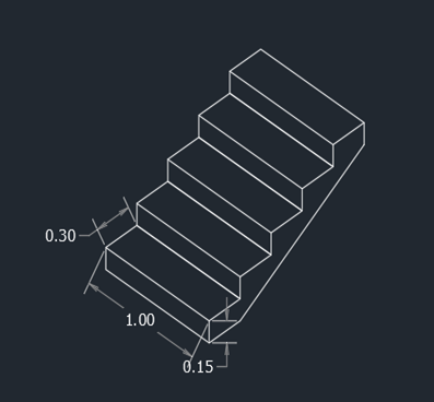
Result - The Isometric view of step is completed.
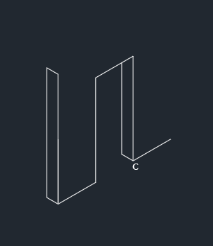
Q6.

Procedure -
Type DS in the command line and press enter.
Unpick snap on and grid on options
Tick on isometric snap in snap type.
This will activates the isometric screen.
Type L in the command line and press Enter.
Specify the start point a.
Take isoplane left
Specify the next point:.30 ,curser towards NW
Specify the next point:3, curser towards N
Specify the next point:.30, curser towards SE
Specify the next point:.3, curser towards E

Type L in the command line and press Enter.
Specify the start point a.
Take isoplane top
Specify the next point:1 ,curser towards NE
Specify the next point:1 ,curser towards NE
Specify the next point:1 ,curser towards NE

Delete the line BC
Type L in the command line and press Enter.
Specify the start point b.
Take isoplane right
Specify the next point:2.42 ,curser towards N
Take isoplane top
Specify the next point:1 ,curser towards NE
Specify the next point:2.42 ,curser towards E

Type L in the command line and press Enter.
Specify the start point c.
Take isoplane left
Specify the next point:.30 ,curser towards NW
Take isoplane right
Specify the next point:2.12 ,curser towards N
Type L in the command line and press Enter.
Specify the start point a.
Take isoplane top
Specify the next point:1.5 ,curser towards NE
Take isoplane right
Specify the next point:3.25 ,curser towards N
Type L in the command line and press Enter.
Specify the start point d.
Take isoplane left
Specify the next point:.30 ,curser towards NW

Type L in the command line and press Enter.
Specify the start point d.
Specify the next point: e
Specify the next point: f

Delete the line: eg and ag
Type L in the command line and press Enter.
Specify the start point h.
Specify the next point: i
Specify the next point: j

Type DLI or DIMLINEAR on the command line and press Enter.
Give the dimensions as per the drawing.

Result - The Isometric view of gable wall is completed.
Leave a comment
Thanks for choosing to leave a comment. Please keep in mind that all the comments are moderated as per our comment policy, and your email will not be published for privacy reasons. Please leave a personal & meaningful conversation.
Other comments...
Be the first to add a comment
Read more Projects by Mohit Takhalate (36)
Reinforcement detailing of Columns from ETABS output
AIM - Reinforcement detailing of columns in Etabs 2018. The ETABS file for a G+4 building is provided. Run the analysis and design the RCC Moment Resisting Frame. The following challenge deals specifically with two columns at the following grid intersections. 3A 3B Provide details of longitudinal reinforcement for…

01 Apr 2022 07:33 AM IST
Reinforcement Detailing of Beams from ETABS output
Challenge 7 – Detailed design of concrete buildings -1 AIM - Detail design of beams in Etabs 2018.The ETABS file for a G+4 building is provided. Run the analysis and design the RCC Moment Resisting Frame. The following challenge deals specifically with two continuous beams in the 1st floor. …
30 Mar 2022 09:31 AM IST
Project 1_Comparative study of different storey buildings for Seismic forces
24 Mar 2022 02:45 PM IST
Modelling of 25 storey building with the specified properties using ETABS
Challenge 6 – ETABS modelling of a 25 storey building AIM - Model a 25 storey building on ETABS with structural properties as specified below. Ground floor or plinth floor level can be taken at a height of 1.5 metres from the base. Each of the successive 25 storeys has a storey height of 3 metres. Structural…
23 Mar 2022 06:31 AM IST
Related Courses


0 Hours of Content
Skill-Lync offers industry relevant advanced engineering courses for engineering students by partnering with industry experts.


Our Company

4th Floor, BLOCK-B, Velachery - Tambaram Main Rd, Ram Nagar South, Madipakkam, Chennai, Tamil Nadu 600042.

Top Individual Courses
Top PG Programs
Skill-Lync Plus
Trending Blogs
© 2025 Skill-Lync Inc. All Rights Reserved.