


Courses by Software
Courses by Semester
Courses by Domain
Tool-focused Courses
Machine learning
POPULAR COURSES
Success Stories

Project
Aim: To prepare a technical report of simulation of BAJA All-Terrain Vehicle (ATV) under different conditions. Objectives: Carry out a system-level simulation of an all-terrain vehicle and prepare a technical report explaining the model properties & comments on the results. All-Terrain Vehicle An all-terrain vehicle…
Priyal Choudhary
updated on 20 Jun 2022


Aim:
To prepare a technical report of simulation of BAJA All-Terrain Vehicle (ATV) under different conditions.
Objectives:
Carry out a system-level simulation of an all-terrain vehicle and prepare a technical report explaining the model properties & comments on the results.
All-Terrain Vehicle
An all-terrain vehicle (ATV) is defined as a motorized off-highway vehicle designed to travel on four low-pressure or non-pneumatic tires, having a seat designed to be straddled by the operator and handlebars for steering control.
CASE 1
SIMULINK MODEL FOR BAJA ATV WITH CVT :

Major components in the model:
Continuously Variable Transmission Drive (CVT)
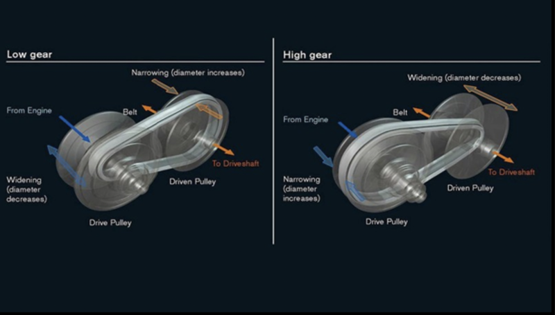
It is better to have gears in transmission since it can optimize engine speed in a variety of driving conditions. That means low gears can provide better acceleration while higher gears can maximize fuel economy. CVTs differ from traditional automatic transmissions in that they don’t have gears that provide “steps” between low- and high-speed operations. Instead, the majority of them work via a pair of variable-diameter, cone-shaped pulleys connected by a steel or composite belt. The halves of each pulley are aligned with connecting belt rides. One side of the pulley is fixed, and the other side is movable, actuated by a hydraulic cylinder. The cylinder can increase or decrease the amount of space between the two sides of the pulley. This allows the belt to ride lower or higher along the walls of the pulley, depending on driving conditions, thereby changing the “gear” ratio.
CVT BLOCK:

Variable transmission Ratio:
Represents a variable ratio gearbox such as implemented by mechanical belt CVT, electric, or hydraulic transmissions. The physical signal input r defines the ratio of input to output angular shaft velocities.
Connections B (base) and F (follower) are technical rotational conserving ports. Specify the relation between base and follower rotation directions with the output shaft rotates parameter.
Engine
Represents a system-level model of spark-ignition and diesel engines suitable for use at the initial stages of modeling when only the basic parameters are available. Optional idle speed and red line controllers are included. The throttle input signal T lies between zero and one and specifies the torque demanded from the engine as a fraction of the maximum possible torque.
Connections F and B are mechanical rotational conserving ports associated with the engine crankshaft and engine block, respectively. Connections P and FC are physical signal output ports through which engine power and fuel consumption rate are reported.
INPUT SIGNAL
A signal builder is used to create signals for the brake and throttle.

CVT Gear Ratio Input:

Torque vs Engine Speed Input:

VEHICLE BODY:
OUTPUT for CASE 1:
VEHICLE SPEED:

It is clear from the graph that the vehicle attains its maximum speed (V=55km/hr) at full throttle =1 after 30 secs and then remains constant. The brake input value is zero, hence it has no effect on velocity.

CVT SHAFT RPM

These graphs show the variation in angular velocities of input and output shafts of the variable gear transmission system. These values differ with respect to the gear ratio.
STUDY 1
CASE2:
SIMULINK MODEL FOR BAJA ATV WITH CVT USING DASHBOARD :

In this model, we have a dashboard that contains knobs to control the inputs. In this case, the inputs - ‘Throttle & Brake’ are not provided using the signal builder. A knob is provided to control both the parameters in real-time for the user.
OUTPUT for CASE 2:
VEHICLE SPEED:

It can be observed from the graph that the velocity of the vehicle increases drastically from 0 to 50 mph when the throttle valve is 0.5 & brake input is 0. Once the braking value increases from 0.1 to 0.5, the velocity of the vehicle decreases to 0 at a constant throttle value. This explains the direct relation of the vehicle velocity with respect to throttle and brake inputs.
CVT SHAFT RPM:

STUDY 2
CASE 1
SIMULINK MODEL FOR BAJA ATV WITH CVT USING LOOKUP TABLE:

CVT BLOCK:

The only difference between this model and the first model is that in this model, the gear ratio input to CVT is provided using a lookup table. The vehicle velocity and shaft rpm outputs are the same as before.
CVT GEAR RATIO:

LOOKUP TABLE VISUALISATION:

OUTPUT for CASE 1
VEHICLE SPEED:

CVT SHAFT RPM:

Both results are the same as that of the first case: - SIMULINK MODEL FOR BAJA ATV WITH CVT since the input parameters are the same.
STUDY 2
CASE 2
SIMULINK MODEL FOR BAJA ATV WITH CVT USING LOOKUP TABLE & DASHBOARD:

In this model a dashboard is used to control the inputs - ‘Throttle & Brake’ with knobs.
OUTPUT for CASE 2:
VEHICLE SPEED :

This graph is similar to that of the CVT dashboard case. The variation in vehicle velocity can be observed with changes in throttle and brake inputs. With the increase in braking value, the speed of the vehicle decreases. On the other hand, increasing the throttle leads to increased vehicle velocity.
CVT SHAFT RPM:

This graph indicates the variation in rpm of primary and secondary shafts with respect to input parameters.
CONCLUSION
Thus we have successfully analyzed 4 different models of BAJA ATV WITH CVT and recorded the outputs:- (Vehicle velocity & CVT shaft rpm) with respect to variations in input throttle and brake.
Leave a comment
Thanks for choosing to leave a comment. Please keep in mind that all the comments are moderated as per our comment policy, and your email will not be published for privacy reasons. Please leave a personal & meaningful conversation.
Other comments...
Be the first to add a comment
Read more Projects by Priyal Choudhary (13)
Project 1 - Interfacing a 16*2 LCD with Arduino using I2C protocol
//I2C MASTER CODE #include //Library for I2C Communication functions#include //Library for I2C Communication functionsLiquidCrystal lcd(2,7,8,9,10,11); //Define LCD Module Pins (RS,EN,D4,D5,D6,D7) void setup(){lcd.begin(16,2); //Initialize LCD displaylcd.setCursor(0,0); //Sets Cursor at first line of displaylcd.print("Circuit…

29 Jan 2023 04:45 AM IST
Project 2 - Measuring the distance of an object using ultrasonic sensor and also smoothen the sensor data using moving average filter
int inches = 0;int cm = 0;long readUltrasonicDistance(int triggerPin, int echoPin){pinMode(triggerPin, OUTPUT); // Clear the trigger digitalWrite(triggerPin, LOW); delayMicroseconds(2); // Sets the trigger pin to HIGH state for 10 microsecondsdigitalWrite(triggerPin, HIGH);delayMicroseconds(10);digitalWrite(triggerPin,…
27 Jan 2023 09:43 AM IST
Project 1 - Interfacing a 16*2 LCD with Arduino using I2C protocol
Master code: #include //Library for LCD display function LiquidCrystal lcd(12, 11, 5, 4, 3, 2); //Define LCD Module Pins (RS,EN,D4,D5,D6,D7) int val1=A4; int val2=A5; void setup() { lccd.begin(16,2); } void loop() { lcd.setCursor(0,0); //Sets Cursor at line one of LCD…
24 Jan 2023 10:40 AM IST
Project 2 - Measuring the distance of an object using ultrasonic sensor and also smoothen the sensor data using moving average filter
int inches = 0;int cm = 0;long readUltrasonicDistance(int triggerPin, int echoPin){pinMode(triggerPin, OUTPUT); // Clear the trigger digitalWrite(triggerPin, LOW); delayMicroseconds(2); // Sets the trigger pin to HIGH state for 10 microsecondsdigitalWrite(triggerPin, HIGH);delayMicroseconds(10);digitalWrite(triggerPin,…
24 Jan 2023 09:47 AM IST
Related Courses


0 Hours of Content
Skill-Lync offers industry relevant advanced engineering courses for engineering students by partnering with industry experts.


Our Company

4th Floor, BLOCK-B, Velachery - Tambaram Main Rd, Ram Nagar South, Madipakkam, Chennai, Tamil Nadu 600042.

Top Individual Courses
Top PG Programs
Skill-Lync Plus
Trending Blogs
© 2025 Skill-Lync Inc. All Rights Reserved.