


Courses by Software
Courses by Semester
Courses by Domain
Tool-focused Courses
Machine learning
POPULAR COURSES
Success Stories

Week-6 Challenge: EV Drivetrain
Pratik Mankar AIM To get to know types of converters are used in Electric and Hybrid Electric Vehicle To find the speed using torque-speed Relation. To develop a mathematical model of a DC Motor for the given equation using simulink. To get to know about induction versus DC brushless motor 1] Which types of power converter…
Pratik Mankar
updated on 01 Aug 2022


Pratik Mankar
AIM
- To get to know types of converters are used in Electric and Hybrid Electric Vehicle
- To find the speed using torque-speed Relation.
- To develop a mathematical model of a DC Motor for the given equation using simulink.
- To get to know about induction versus DC brushless motor
1] Which types of power converter circuits are employed in electric and hybrid electric vehicle?
Converter
A device that increases or decreases the voltage (AC or DC) of a power source depending on application. A converter that increases voltage is called a step-up converter and a converter that decreases voltage is called a step-down converter. In EVs/HEVs step-up and step-down converters are combined into one unit. An application of a step-up converter is converting EV/HEV battery voltage (typically 180-300 volts) to about 650 volts to power the traction motor. An advantage of using a converter to increase voltage from the battery is a smaller and less expensive battery may be used while still utilizing an efficient high voltage motor. An application of a step down inverter would be decreasing the high voltage direct current (DC 180-300 volts) from the HEV/EV battery to low voltage (12-14 volts) DC that can be used to charge the 12 volt auxiliary battery and operate light load devices such as lighting, radio, and windows.
They are 4 main categries of power converter ciruits which are used in Electric and Hybrid Electric Vehicles.
1) AC to DC Converters or Rectifiers
+ Uncontroller Diode Rectifiers
- Single Phase half-wave Rectifier.
- Single Phase center-tapped full-wave Rectifier.
Single phase full-wave Bridge Rectifier.
- Three-Phase Half-Wave Diode Rectifier.
- Three-Phase Full-Wave Diode Bridge Rectifier.
Phase Controller Rectifiers
- Single Phase Half-Wave Rectifier.
- Single Phase Full Wave Mid-Point Rectifier.
- Single Phase Full Wave Bridge Rectifier.
- Three Phase Half-Wave Converter.
- Three Phase full Wave Converter.
2) DC to DC Converter.
- Step-down Chopper or Buck Converter.
- Step-up Chopper or Boost Converter.
- Buck/Boost Converter.
3) AC to AC Converters.
- AC/AC Voltage Converters.
- AC/AC Frequency Converters.
- Cycloconverters.
- Matrix Converter.
- Hybrid Matrix Converter.
4) DC to AC Converter or Inverters.
1) AC to DC Converters
EVs release no tail pipe air pollutants at the place where they are converter. They also typically generate less sound pollution than an indoor combustion engine vehicle, whether at rest or in motion. Adaptation of EVs would have a big net environmental benefit. In modern era almost every household electronics works on DC but we got AC from power generation via transmission lines because AC can be transmitted more efficiently than DC in lower cost.AC to DC converter uses rectifier to turn on AC input into DC output regulators to adjust the voltage level and reservoir capacitor to smooth the pulsating DC.
AC/DC converter can have more than one output and may feature overcurrent and overvoltage. High frequency transformer are found most prominently in any machinery or device that requires level of voltage or current. The transformer was originally intended to be connected to a H bridge which supplies the primary coil with high frequency voltage pulse to be converted into a higher voltage transferred to a rectifier unit. An electric-vehicle battery (EVB) additionally to the traction battery specialty systems used for industrial (or recreational) vehicles, are batteries want to power the system of a battery electric vehicle (BEVs). These batteries are usually a secondary (rechargeable) battery. Electric vehicle batteries also known as traction batteries is a battery that provides power to electric motors.
AC to DC Converter

The AC/DC converter consists of a power factor correction (PFC) which converts input AC voltage into DC voltage, an H-bridge circuit which converts the DC voltage into high-frequency AC voltage, a high-frequency transformer which regulates transformation and insulation, and a circuit which rectifies and smooths high-frequency AC voltage.One is that the coil parts, such as the transformer and the choke coil, contribute to an increase in the volume and weight of the AC/DC converter. Generally, an AC/DC converter has higher output power than that of a DC/DC converter for driving auxiliaries, and accordingly AC/DC converter’s coil parts occupy a larger space. As the AC/DC converter is also equipped with a reactor for the PFC, the coil parts alone weigh as much as 20-30% of the total weight of the AC/DC converter.Another problem is that the AC/DC converter involves large power loss in high-frequency switching. While the increase of switching frequency can reduce the volume of coil parts, power loss by the power device increases. Therefore, for a downsized high-efficiency AC/DC converter, we need to review the circuit diagram to reduce the volume of coil parts and the power loss in switching frequency.
2) DC to DC Converter.
The different configurations of EV power supply show that at least one DC/DC converter is necessary to interface the FC, the Battery or the Supercapacitors module to the DC-link. In electric engineering, a DC to DC converter is a category of power converters and it is an electric circuit which converts a source of direct current (DC) from one voltage level to another, by storing the input energy temporarily and then releasing that energy to the output at a different voltage. The storage may be in either magnetic field storage components (inductors, transformers) or electric field storage components (capacitors). DC/DC converters can be designed to transfer power in only one direction, from the input to the output. However, almost all DC/DC converter topologies can be made bi-directional. A bi-directional converter can move power in either direction, which is useful in applications requiring regenerative braking. The amount of power flow between the input and the output can be controlled by adjusting the duty cycle (ratio of on/off time of the switch). Usually, this is done to control the output voltage, the input current, the output current, or to maintain a constant power.

In case of interfacing the Fuel Cell, the DC/DC converter is used to boost the Fuel Cell voltage and to regulate the DC-link voltage. However, a reversible DC/DC converter is needed to interface the SCs module. A wide variety of DC-DC converters topologies, including structures with direct energy conversion, structures with intermediate storage components (with or without transformer coupling), have been published ( Lachichi & Schofield, 2006),(Yu & Lai,2008), (Bouhalli et al.,2008).
Considerations are essential for Automotive Applications.
-
Light weight,
-
High efficiency,
-
Small volume,
-
Low electromagnetic interference,
-
Low current ripple drawn from the Fuel Cell or the battery,
-
The step up function of the converter,
-
Control of the DC/DC converter power flow subject to the wide voltage variation on the converter input.
Each converter topology has its advantages and its drawbacks. For example, The DC/DC boost converter does not meet the criteria of electrical isolation. Moreover, the large variance in magnitude between the input and output imposes severe stresses on the switch and this topology suffers from high current and voltage ripples and also big volume and weight. A basic interleaved multichannel DC/DC converter topology permits to reduce the input and output current and voltage ripples, to reduce the volume and weight of the inductors and to increase the efficiency. These structures, however, can not work efficiently when a high voltage step-up ratio is required since the duty cycle is limited by circuit impedance leading to a maximum step-up ratio of approximately 4. Hence, two series connected step-up converters would be required to achieve the specific voltage gain of the application specification. A full-bridge DC/DC converter is the most frequently implemented circuit configuration for fuel-cell power conditioning when electrical isolation is required. The full bridge DC/DC converter is suitable for high-power transmission because switch voltage and current are not high. It has small input and output current and voltage ripples. The full-bridge topology is a favorite for zero voltage switching (ZVS) pulse width modulation (PWM) techniques.
3) AC to AC Converters.
AC/AC converters connect an AC source to AC loads by controlling amount of power supplied to the load. This converter converts the AC voltage at one level to the other by varying its magnitude as well as frequency of the supply voltage. These are used in different types of applications including uninterrupted power supplies, high power AC to AC transmission, adjustable speed drives, renewable energy conversion systems and aircraft converter systems. AC to AC converters is used for converting the AC waveforms with one particular frequency and magnitude to AC waveform with another frequency at another magnitude. This conversion is mainly required in case of speed controlling of machines, for low frequency and variable voltage magnitude applications as well. We know that there are different types of loads that work with different types of power supplies like single-phase, three-phase supply, and the supplies can be differentiated based on the voltage and frequency range also.
We require a particular voltage and particular frequency for operating some special devices or machines. For speed control of induction motors, AC to AC converters (Cycloconverters) is used majorly. For obtaining a desired AC power supply from the actual power supply, we need some converters called AC to AC converters.
AC/AC Voltage Converters
These converters control the rms value of output voltage at a constant frequency. The common application of these converters includes starting of AC motors and controlling power to heaters. A single phase AC/AC voltage converter consists of a pair of anti-parallel thyristors along with a control circuit as shown in figure below. The other names of this controller are single phase full wave converter and AC voltage controller. During positive half cycle of the input signal, thyristor-1 is forward biased and it starts conducting, when the triggering is applied. Thus the power flows from source to load. In negative half cycle of the input, thyristor-2 is forward biased and starts conducting when it is triggered, while thyristor-1 is turned OFF by natural commutation. By varying the triggering or conduction angel of each thyristor during each half-cycle, the magnitude of voltage appeared across the load is controlled. The other popular form of AC voltage controller is the use of TRIAC in place of two anti-parallel thyristors. The figure below shows TRIAC based AC controller along with triggering control circuit. Here diac controls the positive and negative triggering to the TRIAC so that average output voltage to the load is controlled.
AC/AC frequency Converters
These converters are mainly used for varying the frequency of the input source to desired level of the load. An AC/AC frequency converter changes the frequency of input voltage/current of the load compared to the frequency of the source.Some of these converters may control magnitude of voltage besides the frequency control. These are mainly used for adjusting the speed of AC drives and also for induction heating.
Cycloconverters.
A cycloconverter (also known as a cycloinverter or CCV) converts a constant voltage, constant frequency AC waveform to another AC waveform of a different frequency. A cycloconverter achieves this through synthesizing the output waveform from segments of the AC supply (without an intermediate DC link. The main forms of electrical energy commonly available are constant DC (Direct Current) and constant AC (Alternating Current). Often though, we need to swap between AC and DC, change the frequency, or swap from constant to variable power. For these conversion purposes, several converters like inverters, rectifiers, DC Choppers and cycloconverters are employed. The cycloconverters can in fact transfer AC power of a fixed frequency to the AC power of a different frequency. The cycloconverter converts AC to AC whilst changing only the frequency. Hence it is also known as a frequency changer. Normally, the output frequency is less than the input frequency. There are no DC stages in between this conversion process. The implementation of the control circuit is complicated due to a large number of SCRs (Silicon controlled Rectifiers ). Microcontroller or DSP or microprocessor is used in control circuits.
There are two main types of cycloconverters:
- Blocking mode Cycloconverters
- Circulating current Cycloconverters
Matrix Converter
Matrix converters are used for converting AC to AC directly without using any DC link for increasing the reliability and efficiency of the system by reducing the cost and losses of the DC-link storage element. Matrix converter consists of the bidirectional switches that practically don’t exist at present but can be realized by using the IGBTs, and these are capable of conducting current and blocking voltage of both polarities. Since the cyclo-converters satisfactorily work only for a certain range of frequencies, matrix converters are invented that has unrestricted frequency conversion capability. These are constructed using full-controlled static devices, mostly uses bidirectional switches. With the use of these switches in three-phase matrix converters, any phase of the load can be connected to any phase of the input supply. By using pulse width modulation techniques, the load frequency and voltages are controlled from zero value to their maximum values.
Hybrid Matrix Converter
The matrix converters that convert AC/DC/AC are termed as Hybrid matrix converter, and similar to the matrix converters, these hybrid converters also don’t use any capacitor or inductor or DC link.These are again classified into two types based on the number of stages they take for conversion, if the voltage and current both are converted in a single stage, then that converter can be called as a Hybrid Direct Matrix Converter.If the voltage and current are converted in two different stages, then that converter can be called a Hybrid Indirect Matrix Converter.
4) DC to AC Converter or Inverters.
In most of the mini electronic projects, the conversion of DC voltage to AC voltage is a common problem. In any circuit, we can observe that if we design a circuit that takes the AC input and gives DC output. But, if we want to change the circuit from DC to AC, a DC to AC converter circuit is used. The inverter (converter) is frequently required in the circuits like where DC to AC conversion is not possible. So, an inverter circuit is employed for converting the DC to AC converter. The converter is a power electronic device, used to convert DC to AC. These devices use switching devices. The DC to AC conversion can be done among 12V, 24V, 48V to 110V, 120V, 220V, 230V, 240V with supply frequency 50Hz/60Hz. For a better understanding of this concept here is a simple 12V DC to 220V AC Converter circuit which is designed to convert DC to AC.


DC to AC converters is mainly designed for changing a DC power supply to an AC power supply. Here, DC power supply is comparatively stable as well as positive voltage source whereas AC oscillates approximately a 0V base stage, typically in a sinusoidal or square or mode. The common inverter technology used in electronics is to convert a voltage source from a battery into an AC signal. Generally, they operate with 12 volts and commonly used in applications like automotive, lead-acid technology, photovoltaic cells, etc. A transformer coil system & a switch is the simple circuit used for an inverter. A typical transformer can be connected toward the DC signal’s input through a switch to oscillate back quickly. Due to the current flow in bi-directional in the primary coil of the transformer, an alternating current signal is an output throughout the secondary coils.
2] An Electric Vehicle's powertrain with 72V battery pack in shown in the diagram below. The duty ratio for acceleration operation is 'd1' and for the braking operation the duty ratio is 'd2'.
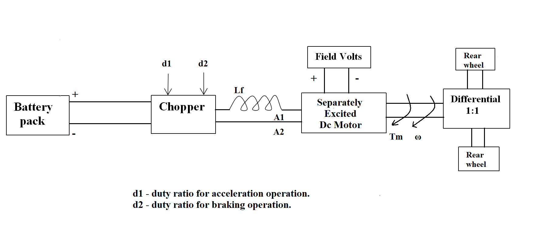
The other parameters of the electric vehicle is given below,
Motor and Controller Parameters:
Rated Armature voltage= 72 V
Rated armature current= 400 A
Ra= 0.5Ω, KΦ= 0.7 Volt second
Chopper Switching frequency= 400 Hz
The vehicle speed-torque characteristics are given by the below equation
![]()
What is EV steady state speed if duty cycle is 70 %?
Data:-
Rated Armature voltage= 72 V
Rated armature current= 400 A
Ra= 0.5Ω,
KΦ= 0.7 Volt second
Chopper Switching frequency= 400 Hz
W = ( V/KΦ))-(RaT/KΦ)^2)
W = (72*0.7/0.7)-((0.5*T)/(0.7*0.7))
W = 72 - 1.0204T
1------- T = 69.2 - 0.98 W
Tv = 24.7 + ( 0.0051)w^2
substituting (1)
0.005W^2 + 0.98W -44.5 =0
| W = 37.92 rad |
3] Develop a mathematical model of a DC Motor for the below equation using Simulink.
Draw a model for the above equation.
Let V = 50.4 Volts
Blocks used in Simulink:
- Constant Block
- Product Block
- Sum Block
- Scope Block
- Square Block
- Ramp Block
Procedure:
- We need to connect the constant voltage block and motor constant block with product block to get this equation V/Kϕ.
- We need to get the constant resistance block, Ramp block as Torque, Square block for motor constant to get this equation Ra/Kϕ^2 .T.
- We need to use sum block to get the equation of V/Kϕ - Ra/Kϕ^2 .T
- The Scope block is connected to the output of sum block.
- The result is viewed in the scope block.

Output:-

Result:
Thus the mathematical model of a DC Motor is implemented using simulink.
4] Refer to the blog on below topic:
Induction Versus DC brushless motors by Wally Rippel, Tesla
Explain in brief about author’s perspective.
Wally Rippel, author writing this blog, has experience in the General Motors, jet propulsion laboratory, Tesla. In this blog, he is saying that there is no best motor for all EV/HEV applications. He starts with the construction and working of DC brushless motor, induction motor also said the various positive and negative points on both the motors.
- There are various motors but only brushless DC and Induction motors are playing major role nowadays in EV and HEVs.
- The construction and working of the brushless DC motor and Induction motor are being discussed. The stators for the 3-phase induction motor and the DC brushless motor are virtually identical. Both the stators have "distributed windings" that are inserted within the stator core. Both drives use 3-phase modulating inverters.
- Both DC brushless and induction drives use motors having similar stators. Both drives use 3-phase modulating inverters. The only differences are the rotors and the inverter controls.
- They are digital controllers, the only control differences are with control code. (DC brushless drives require an absolute position sensor, while induction drives require only a speed sensor; these differences are relatively small.)
- The DC brushless drive can also operate at unity power factor, whereas the best power factor for the induction drive is about 85 percent. This means that the peak point energy efficiency for a DC brushless drive will typically be a few percentage points higher than for an induction drive.
- Also Permanent magnet rotors are also difficult to handle due to very large forces that comes into play when anything ferromagnetic gets close to them.
- Due to improvising technology, there has been alternatives found now and then such as lead-acid batteries, DC brush motors and contact controllers has been replaced by Lithium batteries, brushless DC motors and inverters.
DC Brushless motor:
These motors operate on DC.
Merits:
- Electrical to mechanical energy conversion is optimal
- Can operate at unity power factor
- Rotor cooling is easy & and peak point efficiency is higher
- Less rotor heat is generated
- Torque performance is high compared to induction motor
- Higher starting and running torque compared to induction machine
- Control is comparatively easy.
Demerits:
- Torque remains constant
- Without an inverter the brushless DC motor are useless motor.
- Rotor includes permanent magnets
- Permanent magnets are expensive
- No starting torque when connected to the fixed frequency
- Not easy to change magnetic field with permanent magnet
- Efficiency is less
- As machine size grows magnetic losses increases,load efficiency drops.
Induction motor:
These motors operate on AC supply.
Merits:
- No magnets.
- Has the ability to start under load when directly connected to the fixed frequency
- Desired torque can be achieved
- The motor has the ability to start under load, no inverter is needed
- Efficiency is maximum over dc brushless motor when operated with smart inverter
- The magnetic field can be adjustable
- As machine size grows, losses are not necessary to grow.
- Cost Advantage over PM machine
Demerits:
- Stabilization of torque, speed, temperature is difficult.
- Torque performance is low compared to DC motor.
- Limited starting and limited running torque when compared to DC motor
- The control laws are more difficult and complex to understand
- The best power factor is about 85%
Conclusion:-
After analyzing the merits and demerits and above point disscus of both the motor, Wally Rippel's conclusion is that DC brushless dominates in the hybrid and coming plug-in hybrid, and induction drives will likely maintain dominance for the high-performance pure electric. The selection of motors is mostly based on the application.
Leave a comment
Thanks for choosing to leave a comment. Please keep in mind that all the comments are moderated as per our comment policy, and your email will not be published for privacy reasons. Please leave a personal & meaningful conversation.
Other comments...
Be the first to add a comment
Read more Projects by Pratik Mankar (13)
Week 1 Understanding Different Battery Chemistry
Pratik Mankar AIM To understand different Battery chemistry. OBJECTIVES 1] Prepare a table which includes materials & chemical reactions occurring at the anode and cathode of LCO, LMO, NCA, NMC, LFP and LTO type of lithium ion cells.Give your detailed explanation on it. 2]Compare the differences between…

24 Jan 2023 04:09 AM IST
Final Project: Electric Rickshaw modelling
Pratik Mankar AIM Design of an Electric Rickshaw using MATLAB Simulink (three wheel passenger vehicle). ABSTRACT In this project, we work to create the MATLAB model of the ELECTRIC RICKHAEW by doing a PM brushed type DC motor and a suitable Lithium-Ion battery for the motor. Before this, we will remember…
16 Jan 2023 04:36 PM IST
Project-1: Modelling an electric Car with Li-ion battery
Pratik Mankar AIM To Create a MATLAB model of an electric car in which we uses which uses lithium ion battery and suitable motor choosing a suitable blocks from the Powertrain block set and Implement the Vehicle Speed by using PI Controller and generate the accelerator and brake commands. OBJECTIVES To prepare the…
04 Jan 2023 04:18 AM IST
Project 1 (Mini Project on Vehicle Direction Detection
Pratik Mankar MBD Live Batch 2 Mini Project - Vehicle Direction Determination AIM To create the Vehicle Direction Determination model according to the given requirements. INTRODUCTION Identifying the direction of the vehicle is one of the important & diverse features in Autonomous driving…
30 Sep 2022 11:50 AM IST
Related Courses


Skill-Lync offers industry relevant advanced engineering courses for engineering students by partnering with industry experts.


Our Company

4th Floor, BLOCK-B, Velachery - Tambaram Main Rd, Ram Nagar South, Madipakkam, Chennai, Tamil Nadu 600042.

Top Individual Courses
Top PG Programs
Skill-Lync Plus
Trending Blogs
© 2025 Skill-Lync Inc. All Rights Reserved.