Courses by Software
Courses by Semester
Courses by Domain
Tool-focused Courses
Machine learning
POPULAR COURSES
Success Stories
Project 1 (Mini Project on Vehicle Direction Detection
Pratik Mankar MBD Live Batch 2 Mini Project - Vehicle Direction Determination AIM To create the Vehicle Direction Determination model according to the given requirements. INTRODUCTION Identifying the direction of the vehicle is one of the important & diverse features in Autonomous driving…
Pratik Mankar
updated on 30 Sep 2022
Pratik Mankar
MBD Live Batch 2
Mini Project - Vehicle Direction Determination
AIM
To create the Vehicle Direction Determination model according to the given requirements.
INTRODUCTION
Identifying the direction of the vehicle is one of the important & diverse features in Autonomous driving & Advanced Driver Assistance Features. This particular sub-feature of identifying the direction of vehicle is basically identifying the direction the vehicle is taking based on the camera input.
Camera reads the road signs & stores into its memory with unique values for left turn, right turn & straight drive. Depending on the direction it is taking, final indication is given to the driver – as an indication if he is driving in the recommended direction or not.
Vehicle Direction Determination can also be coupled along - side features like GPS systems to identify whether the vehicle is reaching its destination in an optimized manner. This sub feature can also be used along with Lane Detection, Highway Warning, Ramp Entry / Exit in Wrong Way Detection etc.

Vehicle examination is critical undertaking in different apllications.it is an important process in several purposes. various such application are driver assistance system ,electronic toll collection, intelligent parking system. particularly I wrongdoing anticipation and mischance examination the assignment cal give helpful data.
One such application in order to enhance the detection of vehicles is to determine the direction of vehicles. using the increasing need for security consciousness.
Identifying the direction of vehicle is one of the important and diverse features in autonomous driving and advance driver assistance features this particular sub features of identifying the direction of vehicle is basically identifying the direction of vehicle is taking based on the camera input.
Camera reads the road signs and stores into its memory with unique value for left turn ,right turn, straight drive. Depending on the direction it is taking final indication is given to the driver as an indication if he is driving n the recommended direction or not.
OBJECTIVE
- Development of MATLAB Simulink model as per requirement.
- Tag the requirements to the simulink model; tagging requirement 1 & requirement 2 to their corresponding subsystems is fine.
- MBD compliant changes, Data Dictionary creation & code generation is added advantage, and that is not scope of this project.
- If choosing code generation, Storage class for Input signals: ImportedExtern; Storage class for Output signal: Export to File; Storage class for local signals: localizable; Storage class for calibration signals: Const.
- Choose sample time for all signals as 0.01s.
Requirement - 1
- Steering wheel input as yaw rate (Signal name: SteeringWheel_YawDegreeInput) is the input for this system.
- This is compared against 3 angular values, one each for left turn, right turn & straight drive (Calibration Values: Right_Turn_AngularLimit, Left_Turn_AngularLimit, Straight_Drive_Steering_Angle) to say which specific direction the steering wheel is turning towards.
- Use switch blocks to compare & develop this requirement. Keep this requirement in a subsystem & output of this requirement is a local signal (Signal Name: Vehicle_Turn_Status).
Requirement – 2
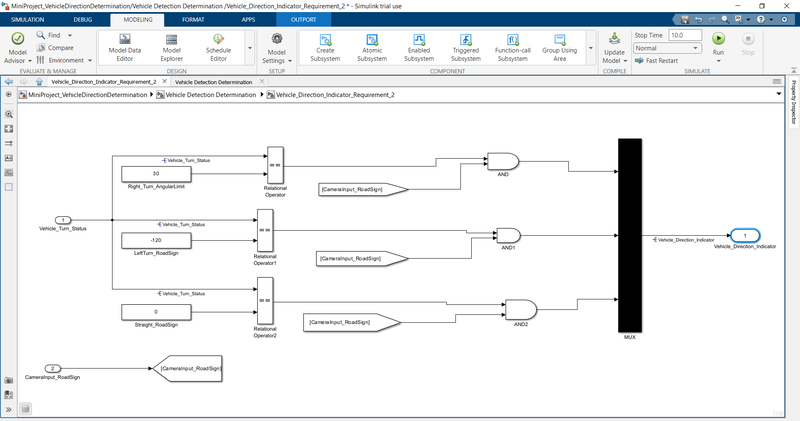
- Keep this requirement as a separate subsystem. Inputs to this requirement are local signal from requirement 1 (Signal Name: Vehicle_Turn_Status) & an input signal from camera (Signal Name: CameraInput_RoadSign), which confirms the occurrence of a road sign.
- Signal Vehicle_Turn_Status is compared against calibration values (Calibration Values: RightTurn_RoadSign, LeftTurn_RoadSign, Straight_RoadSign), if each of them is found equal, then each of the three corresponding output is compared against the camera input signal,
- Using a logical operator block, only one among them is finally given as output signal (Signal Name: Vehicle_Direction_Indicator).
Signals & Calibration Data List
|
Signal / Calibration Name |
Signal Type |
Data Type |
Dimension |
Min |
Max |
Initial Value |
Units |
|
SteeringWheel_YawDegreeInput |
Input |
Int16 |
1 |
-180 |
180 |
- |
Deg |
|
CameraInput_RoadSign |
Input |
Boolean |
1 |
0 |
1 |
- |
- |
|
Vehicle_Turn_Status |
Local |
Int16 |
1 |
-180 |
180 |
- |
Deg |
|
Right_Turn_AngularLimit |
Calibration |
Int16 |
[1 1] |
-180 |
180 |
30 |
Deg |
|
Left_Turn_AngularLimit |
Calibration |
Int16 |
[1 1] |
-180 |
180 |
-120 |
Deg |
|
Straight_Drive_Steering_Angle |
Calibration |
Int16 |
[1 1] |
-180 |
180 |
0 |
Deg |
|
RightTurn_RoadSign |
Calibration |
Int16 |
[1 1] |
-180 |
180 |
30 |
|
|
LeftTurn_RoadSign |
Calibration |
Int16 |
[1 1] |
-180 |
180 |
-120 |
|
|
Straight_RoadSign |
Calibration |
Int16 |
[1 1] |
-180 |
180 |
0 |
|
|
Vehicle_Direction_Indicator |
Output |
Boolean |
1 |
0 |
1 |
- |
- |
STEP 1
DESIGNING THE MODEL
This the main model of subsystem that having two inputs SteeringWheel_YawDegreeInput and CameraInput_RoadSign entering into the Vehicle Detection Determination subsystem and one output Vehicle_Direction_Indicator.


Requirement - 1
Vehicle_Turn_Status_Subsystem
- Steering wheel input as yaw rate (Signal name: SteeringWheel_YawDegreeInput) is the input for this system.
- This is compared against 3 angular values, one each for left turn, right turn & straight drive (Calibration Values: Right_Turn_AngularLimit, Left_Turn_AngularLimit, Straight_Drive_Steering_Angle) to say which specific direction the steering wheel is turning towards.
- Use switch blocks to compare & develop this requirement. Keep this requirement in a subsystem & output of this requirement is a local signal (Signal Name: Vehicle_Turn_Status).


Requirement – 2
Vehicle_Direction_Indicator_Subsystem
- Keep this requirement as a separate subsystem. Inputs to this requirement are local signal from requirement 1 (Signal Name: Vehicle_Turn_Status) & an input signal from camera (Signal Name: CameraInput_RoadSign), which confirms the occurrence of a road sign.
- Signal Vehicle_Turn_Status is compared against calibration values (Calibration Values: RightTurn_RoadSign, LeftTurn_RoadSign, Straight_RoadSign), if each of them is found equal, then each of the three corresponding output is compared against the camera input signal,
- Using a logical operator block, only one among them is finally given as output signal (Signal Name: Vehicle_Direction_Indicator).


REQUIREMENT OF TAGGING
All the requirements are tagged in order for better understandability, anyone who is reviewing the model or who is trying to update the model can get a clear idea of what logic is used in the system. from the requirement manager, we can see what are all are tagged and the description.
Firstly I wrote all requirement in word file then I select my first requirement then I return on model select my first subsystem right click on it then goto requirements and link to selection in word then my subsystem box is highlited and linked.in this way i link my second subsyem with requirement 2.
REQUIREMENT 1 TAG WITH SUBSYSTEM 1

REQUIREMENT 1 TAG WITH SUBSYSTEM 1

STEP 2
MODEL CONFIGURATION
Now from model setting> solver configuration> type-fixed-step >solver- discrete solver>stepsize= 0.01seconds


STEP 3
LINK TO DATA DICTIONARY AND CREAT A NEW SLDD
- Create a sldd file according to the data given in question.
- modeling > link to data dictionary > new( create new sldd file)
- Then access the sldd file from modeling> model explorer>Vehicle Direction Determination> expand external data> design data( input signal and parameters there)


Signals & Calibration Data List.
|
Signal / Calibration Name |
Signal Type |
Data Type |
Dimension |
Min |
Max |
Initial Value |
Units |
|
SteeringWheel_YawDegreeInput |
Input |
Int16 |
1 |
-180 |
180 |
- |
Deg |
|
CameraInput_RoadSign |
Input |
Boolean |
1 |
0 |
1 |
- |
- |
|
Vehicle_Turn_Status |
Local |
Int16 |
1 |
-180 |
180 |
- |
Deg |
|
Right_Turn_AngularLimit |
Calibration |
Int16 |
[1 1] |
-180 |
180 |
30 |
Deg |
|
Left_Turn_AngularLimit |
Calibration |
Int16 |
[1 1] |
-180 |
180 |
-120 |
Deg |
|
Straight_Drive_Steering_Angle |
Calibration |
Int16 |
[1 1] |
-180 |
180 |
0 |
Deg |
|
RightTurn_RoadSign |
Calibration |
Int16 |
[1 1] |
-180 |
180 |
30 |
|
|
LeftTurn_RoadSign |
Calibration |
Int16 |
[1 1] |
-180 |
180 |
-120 |
|
|
Straight_RoadSign |
Calibration |
Int16 |
[1 1] |
-180 |
180 |
0 |
|
|
Vehicle_Direction_Indicator |
Output |
Boolean |
1 |
0 |
1 |
- |
- |

All the inputs, outputs, calibration parameters are saved in SLDD so while simulation the model takes all the values and its parameters from the Simulink Data Dictionary.
SIGNAL RESOLUTION FOR INPUT AND OUTPUT
the inputs and output signals are resolved so the signals will take the values from sldd and pass them to the logical blocks. Otherwise, it may take some junk values if it is unresolved.
MODEL UPDATE
The model update is done by Ctrl-D. this is done to check for any static errors. If there are no errors coming the model is working fine without any errors.
SIMULATION
The model is simulated too for checking for errors and warnings.
CONFIGURATION PARAMETER UPDATE
Various configuration parameters are updated as per the code generation the solver type should be fix for code generation
STEP 4
MODEL ADVISOR
Get a Model Advisor Check>by task>ony check modelling standards with MAB>Run selected checks


STEP 5
CODE GENERATION
/*
 * File: Project_on_Vehicle_Direction_Detection_1634144274.c
 *
 * Code generated for Simulink model 'Project_on_Vehicle_Direction_Detection_1634144274'.
 *
 * Model version                  : 1.12
 * Simulink Coder version         : 10.6 (R2022b) 25-Sep-2020
 * C/C++ source code generated on : Thu Sep 29 18:12:10 2022
 *
 * Target selection: ert.tlc
 * Embedded hardware selection: Intel->x86-64 (Windows64)
 * Code generation objectives: Unspecified
 * Validation result: Not run
 */

#include "Project_on_Vehicle_Direction_Detection_1634144274.h"
#include "Project_on_Vehicle_Direction_Detection_1634144274_private.h"

/* Exported data definition */

/* Definition for custom storage class: ExportToFile */
boolean_T Vehicle_Direction_Indicator; /* '/OR' */

/* Real-time model */
static RT_MODEL_Project_on_Vehicle_D_T Project_on_Vehicle_Direction_M_;
RT_MODEL_Project_on_Vehicle_D_T *const Project_on_Vehicle_Direction_M =
  &Project_on_Vehicle_Direction_M_;

/* Model step function */
void Project_on_Vehicle_Direction_Detection_1634144274_step(void)
{
  int32_T rtb_Vehicle_Turn_Status;

  /* Switch: '/Switch' incorporates:
   *  Constant: '/Left_Turn_AngularLimit'
   *  Constant: '/Right_Turn_AngularLimit'
   *  Inport: '/SteeringWheel_YawDegreeInput'
   *  Switch: '/Switch1'
   */
  if (SteeringWheel_YawDegreeInput > 25) {
    rtb_Vehicle_Turn_Status = 30;
  } else if (SteeringWheel_YawDegreeInput > 0) {
    /* Switch: '/Switch1' incorporates:
     *  Constant: '/Straight_Drive_Steering_Angle'
     */
    rtb_Vehicle_Turn_Status = 0;
  } else {
    rtb_Vehicle_Turn_Status = -120;
  }

  /* End of Switch: '/Switch' */

  /* Logic: '/OR' incorporates:
   *  Constant: '/LeftTurn_RoadSign'
   *  Constant: '/RightTurn_RoadSign'
   *  Constant: '/Straight_RoadSign'
   *  Inport: '/CameraInput_RoadSign'
   *  Logic: '/Logical Operator'
   *  Logic: '/Logical Operator1'
   *  Logic: '/Logical Operator3'
   *  RelationalOperator: '/Relational Operator'
   *  RelationalOperator: '/Relational Operator1'
   *  RelationalOperator: '/Relational Operator2'
   */
  Vehicle_Direction_Indicator = ((CameraInput_RoadSign &&
    (rtb_Vehicle_Turn_Status == 30)) || (CameraInput_RoadSign &&
    (rtb_Vehicle_Turn_Status == -120)) || (CameraInput_RoadSign &&
    (rtb_Vehicle_Turn_Status == 0)));
}

/* Model initialize function */
void Project_on_Vehicle_Direction_Detection_1634144274_initialize(void)
{
  /* (no initialization code required) */
}

/* Model terminate function */
void Project_on_Vehicle_Direction_Detection_1634144274_terminate(void)
{
  /* (no terminate code required) */
}

/*
 * File trailer for generated code.
 *
 * [EOF]
 */
CONCLUSION
I make model of vehicle direction determination model and as per given requirements also i make sldd for it. all input output signals resolved and propageted ,then I check error with model advisor report I passed in that report and my code is generated successfully.In this way I done my project and get result satisfactory.
Leave a comment
Thanks for choosing to leave a comment. Please keep in mind that all the comments are moderated as per our comment policy, and your email will not be published for privacy reasons. Please leave a personal & meaningful conversation.
Other comments...
Be the first to add a comment
Read more Projects by Pratik Mankar (13)
Week 1 Understanding Different Battery Chemistry
Pratik Mankar AIM To understand different Battery chemistry. OBJECTIVES 1] Prepare a table which includes materials & chemical reactions occurring at the anode and cathode of LCO, LMO, NCA, NMC, LFP and LTO type of lithium ion cells.Give your detailed explanation on it. 2]Compare the differences between…
24 Jan 2023 04:09 AM IST
Final Project: Electric Rickshaw modelling
Pratik Mankar AIM Design of an Electric Rickshaw using MATLAB Simulink (three wheel passenger vehicle). ABSTRACT In this project, we work to create the MATLAB model of the ELECTRIC RICKHAEW by doing a PM brushed type DC motor and a suitable Lithium-Ion battery for the motor. Before this, we will remember…
16 Jan 2023 04:36 PM IST
Project-1: Modelling an electric Car with Li-ion battery
Pratik Mankar AIM To Create a MATLAB model of an electric car in which we uses which uses lithium ion battery and suitable motor choosing a suitable blocks from the Powertrain block set and Implement the Vehicle Speed by using PI Controller and generate the accelerator and brake commands. OBJECTIVES To prepare the…
04 Jan 2023 04:18 AM IST
Project 1 (Mini Project on Vehicle Direction Detection
Pratik Mankar MBD Live Batch 2 Mini Project - Vehicle Direction Determination AIM To create the Vehicle Direction Determination model according to the given requirements. INTRODUCTION Identifying the direction of the vehicle is one of the important & diverse features in Autonomous driving…
30 Sep 2022 11:50 AM IST
Related Courses


Skill-Lync offers industry relevant advanced engineering courses for engineering students by partnering with industry experts.
Our Company
4th Floor, BLOCK-B, Velachery - Tambaram Main Rd, Ram Nagar South, Madipakkam, Chennai, Tamil Nadu 600042.
Top Individual Courses
Top PG Programs
Skill-Lync Plus
Trending Blogs
© 2025 Skill-Lync Inc. All Rights Reserved.


