


Courses by Software
Courses by Semester
Courses by Domain
Tool-focused Courses
Machine learning
POPULAR COURSES
Success Stories

Week-7 Challenge: DC Motor Control
Pratik Mankar AIM To run MATLAB demo ' speed control of a DC Motor using BJT H-Bridge'. Modify the model such that armature current doesn't shoot up when motor changes direction from Forward to Reverse.To understand the Four-Quadrant chopper DC Drive ( DC7) Block and compare it with H-Bridge model. To Develop…
Pratik Mankar
updated on 04 Aug 2022


Pratik Mankar
AIM
- To run MATLAB demo ' speed control of a DC Motor using BJT H-Bridge'. Modify the model such that armature current doesn't shoot up when motor changes direction from Forward to Reverse.To understand the Four-Quadrant chopper DC Drive ( DC7) Block and compare it with H-Bridge model.
- To Develop a 2-quadrant chopper using simulink & explain the working of the same with the relevant results.
- To Explain in a brief about operation of BLDC motor.
1. A. Explain a MATLAB demo model named ‘Speed control of a DC motor using BJT H-bridge’.
B. Comment on the armature current shoot-up from the scope results.
C. Refer to the help section of ‘The Four-Quadrant Chopper DC Drive (DC7) block’. Compare it with the H-bridge model.
2. Develop a 2-quadrant chopper using simulink & explain the working of the same with the relevant results. (Refer to article - Multiquadrant operation of motor )
3. Explain in a brief about operation of BLDC motor.
1] A) Explain a MATLAB demo model named ‘Speed control of a DC motor using BJT H-bridge’.
Insulated-Gate Bipolar Transistor.
- IGBT is the short form of Insulated Gate Bipolar Transistor. It is a three-terminal semiconductor switching device that can be used for fast switching with high efficiency in many types of electronic devices. These devices are mostly used in amplifiers for switching/processing complex wave patters with pulse width modulation (PWM).
-
The Insulated Gate Bipolar Transistor (IGBT) is a semiconductor device having three terminals – Gate (G), Emitter (E), and Collector (C). IGBT has been developed by combining the best qualities of both BJT and Power MOSFET.

Advantages of IGBT
- Lower gate-driver requirements
- Lower switching losses
- Smaller snubber circuit requirement
- Less size and cost
- High efficiency
Disadvantages of IGBT
- The switching frequency of insulated gate bipolar transistor (IGBT) is not as high as that of a power MOSFET.
- It cannot block high reverse voltages.
Application Of IGBT
- IGBT are used in dc and ac motor drives
- Used in UPS systems
- Used in power supplies and drivers for solenoids, relays and contactors
Bridge Motor Drvie Using Bipolar Transistor.
An H-bridge is an arrangement of transistors that allows a circuit full control over a standard electric DC motor. That is, an H-bridge allows a microcontroller, logic chip, or remote control to electronically command the motor to go forward, reverse, brake, and coast.
DC Motor
- A DC motor is an electrical machine that converts electrical energy into mechanical energy. In a DC motor, the input electrical energy is the direct current which is transformed into the mechanical rotation. A DC motor is defined as a class of electrical motors that convert direct current electrical energy into mechanical energy.
-
Thus, there are three general methods of speed control of D.C. Motors. Resistance variation in the armature circuit: This method is called armature resistance control or Rheostat control.
- DC motors are used in any number of applications since they have a high starting torque compared to induction motors. Brushed DC motors are easy to miniaturize, and they provide good rotational control as well as high efficiency. Brushless DC motors have a long life due to their lack of wear from brushes, are easy to maintain, and are noiseless.
Speed Control of a DC Motor Using BJT H-Bridge.
The Bipolar Junction Transistor (BJT) when used for power switching applications, operates as an IGBT. When it is conducting (BJT operating in the saturated region), a forward voltage Vf is developed between collector and emitter (in the range of 1 V). Therefore, the IGBT block can be used to model the BJT device.
The IGBT block does not simulate the gate current controlling the BJT or IGBT. The switch is controlled by a Simulink® signal (1/0). The DC motor uses the preset model (5 HP 24V 1750 rpm). It simulates a fan type load (where Load torque is proportional to square of speed). The armature mean voltage can be varied from 0 to 240 V when the duty cycle (specified in the Pulse Generator block) is varied from 0 to 100%.
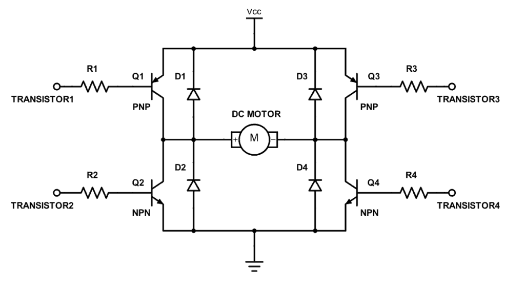
The H-bridge consists of four BJT/Diode pairs (BJT simulated by IGBT models). Two transistors are switched simultaneously: Q1 and Q4 or Q2 and Q3. When Q1 and Q4 are fired, a positive voltage is applied to the motor and diodes D2-D3 operate as free-wheeling diodes when Q1 and Q4 are switched off. When Q2 and Q3 are fired, a negative voltage is applied to the motor and diodes D1-D4 operate as free-wheeling diodes when Q2 and Q3 are switched off.
INPUT :- POWER H-BRIDGE ( simulation Model )

The motor starts in the positive direction with a duty cycle of 75% (mean DC voltage of 180V). At t= 0.5 sec., the armature voltage is suddenly reversed and the motor runs in the negative direction.
OUTPUT:-
AT PULSE WIDTH 75
- Then the switch block is connected to pulse generator through armature voltage control block.
- The H-bridge consists of four BJT/Diode pairs (BJT simulated by IGBT models). Two transistors are switched simultaneously: Q1 and Q4 or Q2 and Q3. When Q1 and Q4 are fired, a positive voltage is applied to the motor and diodes D2-D3 operate as free-wheeling diodes when Q1 and Q4 are switched off. When Q2 and Q3 are fired, a negative voltage is applied to the motor and diodes D1-D4 operate as free-wheeling diodes when Q2 and Q3 are switched off.
- An switch block is splits the power supply into 4 parts they are [p1],[p2],[p3],and [p4]. These input types are in goto form.
- That block is used to send signals to From blocks that have the specified tag. If tag visibility is 'scoped', then a Goto Tag Visibility block must be used to define the visibility of the tag. The block icon displays the selected tag name (local tags are enclosed in brackets, [], and scoped tag names are enclosed in braces, {}).
- Therefore the four types of inputs are connected to transistor Q1,Q2,Q3, and Q4 through from block. An from block Receive signals from the Goto block with the specified tag. If the tag is defined as 'scoped' in the Goto block, then a Goto Tag Visibility block must be used to define the visibility of the tag. After 'Update Diagram', the block icon displays the selected tag name (local tags are enclosed in brackets, [], and scoped tag names are enclosed in braces, {}).
- SWITCHES:
Q1 and Q4 - Forward motoring
Q2 and Q3 - reverse motoring
- This formation is called an H-bridge. An H-bridge is an arrangement of transistors that allows a circuit full control over a standard electric DC motor.
- The DC motor is connected to the battery and the mechanical input of DC motor is initiated as torque.
- Load Torque proportional to
square of speed
T=k*w^2 - Torque for mechanical input of DC motor also switched by go to and from blocks.
- The output from the DC motor is connected with bus sector whereas the speed is plotted in the scope. A conversion of speed from rad/s to rpm is held between the bus sector to scope using converter block.

In this current output the amount of current is acted is shown as the graphical representation during the period of duty cycle. This scope shows IGBT current and Diode current passed in the quadrant Q3 and D3.
where Q3 is represented as IGBT current and D3 is represented as Diode current in scope.
This graph shows when the switch Q3 is OFF on the starting stage of current flow and Diode current is ON on that stage.
During the 1 sec of time D3 switch is ON that are given according to pulse generator and after the time period of 1 sec D3 switch is OFF.
An IGBT current is acted after 0.5sec and Q3 switch remains ON.

The speed and armature current is obtained by the DC motor and load torque is calculated by
Load Torque proportional to
square of speed
T=k*w^2
In starting point, there is a sudden shootup is acted.
In this scope shows that speed is increased in certain period of time and that time armature current is in positive terminal whereas load torque also moves forward.
After the time period of 1 sec which is given in pulse generator sudden shoot-up is acted and speed gets decreased in that time armature current is in negative terminal whereas torque act as reverse action.
Here the sudden shoot up is acted while the armature current is processed at a positive and negative terminal.
'Scope' shows motor speed, armature current and load torque and 'Currents' shows currents flowing in BJT Q3 and diode D3.
Digram H-Bridge used controlling Direction-DC-Motor

- To get steadier and smoother current floe we need to decrease and control the duty cycle.This shoot up happens because of the switching in the circuit that cause heat losses during switching.
- To avoid these losses, we use HEAT SINK material to dissipate the heat. From this the motor can change its direction of rotation easily and very smoothly.
B) Comment on the armature current shoot-up from the scope results.
Speed Control Of a DC Motor Using BJT H-Bridge

AT PULSE WIDTH 50
One simple and easy way to control the speed of a motor is to regulate the amount of voltage across its terminals and this can be achieved using “Pulse Width Modulation”
For experimental section we will reduce the pulse width (that is refer as the duty cycle) of pulse generator block as 50% at the same time period.
The input of the P1,P2,P3 and P4 are also changed according to the drive cycle. When the Q1 and Q4 switch is ON the motor is generated as forward direction that state Q3 switch and Q2 switch is in OFF.
When the Q2 and Q3 switch is ON the motor is generated as reverse direction that state Q1 and Q4 switch is in OFF condition.
The changes made as 50% of pulse width are shown as below

Output

Here we see that the sudden shoot up is not acted by comparing with 75 of pulse width. Same cycle time is followed in this experiment also.
In this observation a starting current is generated as diode current for time period of 1 sec then IGBT current is acted while the diode current is being stoped.
where Q3 is represented as IGBT current and D3 is represented as Diode current in scope.
This graph shows when the switch Q3 is OFF on the starting stage of current flow and Diode current is ON on that stage.
During the 1 sec of time D3 switch is ON that is given according to the pulse generator and after the time period of 1 sec D3 switch is OFF. An IGBT current is acted after 1 sec and Q3 switch remains ON.
There will be a little variation are shown in the graph at the starting point of current but the complete reduction of shoot up are not held here.

In this above scope, a flow of armature current is displayed and speed, load torque is also displayed.
The changes are made in pulse width as 50% from the pulse generator and results are shown that voltage fluctuation is held in starting point of forward state and reverse state.
That sudden fluctuation is reduced in this experiment by reducing the pulse width(duty cycle of motor) of the input supply. An changes are also held in speed and load torque where the constant level of speed and torque is acted in above scope compare with 75% of pulse width.
Time period of forward and reverse action is maintained as same as the previous duty cycle.
In this observation the shoot up is reduced when motor changes direction from forward to reverse compared to 75 of pulse width.
AT PULSE WIDTH 35
In previous experiment there will be an reduction of shoot up(fluctuation) is observed, But we want to modify the model such that armature current doesn’t shoot up when motor changes direction from forward to reverse.
For the experimental section, we will reduce the pulse width (that is refer as the duty cycle) of pulse generator block as 35% at the same time period.
The input of the P1,P2,P3 and P4 are also changed according to the drive cycle. When the Q1 and Q4 switch is ON the motor is generated as forward direction that state Q3 switch and Q2 switch is in OFF.
When the Q2 and Q3 switch is ON the motor is generated as reverse direction that state Q1 and Q4 switch is in OFF condition.
The changes made as 35 of pulse width are shown as below,

Output

This graph shows that IGBT current and diode current flow from transistor Q3 and D3 after changing the pulse width(duty cycle) as 35.
where Q3 is represented as IGBT current and D3 is represented as Diode current in scope.
This graph shows when the switch Q3 is OFF on the starting stage of current flow and Diode current is ON on that stage.
During the 1 sec of time D3 switch is ON that are given according to pulse generator and after the time period of 1 sec D3 switch is OFF. An IGBT current is acted after 1 sec and Q3 switch remains ON.
The flow of current is not much varied in IGBT current and Diode current when we compared it with 75 of pulse width. The shoot up(fluctuation) is less in this duty cycle when motor changes direction from forward to reverse.

In this above scope a flow of armature current is displayed and speed, load torque are also displayed.
From the above experiments shows that shoot up (voltage fluctuation) doesn't appear while we reducing the pulse width (duty cycle) in pulse generator. But raise in fluctuation of armature current is not completely acted during motor changes direction from forward to reverse.
Because starting point of current is raised during forward and reverse direction of motor. voltage fluctuation is acted on that point.
Time period of forward and reverse action is maintained as same as the previous duty cycle.
By the reduction of duty cycle(pulse width)as 42 we observed that armature current doesn’t shoot up when motor changes direction from forward to reverse. The constant flow of armature current is observed in this experiment during motor changes direction forward to reverse.
Therefore the shoot up is completely minimized by this Pulse Width Modulation method.
C) Refer to the help section of ‘The Four-Quadrant Chopper DC Drive (DC7) block’. Compare it with the H-bridge model.
A chopper is a static device that converts fixed DC input voltage to a variable DC output voltage. It is basically a high speed ON/OFF semiconductor switch. Chopper is a DC-DC converter circuit. It is convert a fixed dc into variable DC .

 week 7_1659498136.png)
Four Quadrant Operation of DC Motor
Four Quadrant Operation of any drives or DC Motor means that the machine operates in four quadrants. They are Forward Braking, Forward motoring, Reverse motoring and Reverse braking.A motor operates in two modes – Motoring and Braking. A motor drive capable of operating in both directions of rotation and of producing both motoring and regeneration is called a Four Quadrant variable speed drive. In motoring mode, the machine works as a motor and converts the electrical energy into mechanical energy, supporting its motion. In braking mode, the machine works as a generator and converts mechanical energy into electrical energy and as a result, it opposes the motion. The Motor can work in both, forward and reverse directions, i.e., in motoring and braking operations.
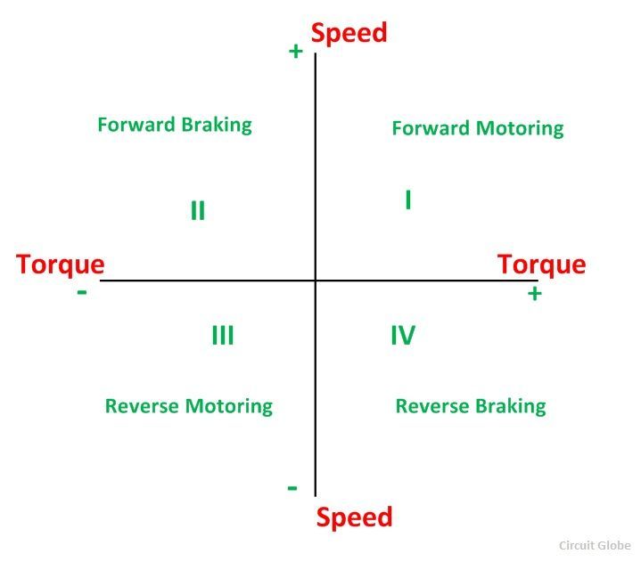
The product of angular speed and torque is equal to the power developed by a motor. For the multi-quadrant operation of drives, the following conventions about the signs of torque and speed are used. When the motor is rotated in the forward direction the speed of the motor is considered positive. The drives which operate only in one direction, forward speed will be their normal speed. In loads involving up and down motions, the speed of the motor which causes upward motion is considered to be in forward motion. For reversible drives, forward speed is chosen arbitrarily. The rotation in the opposite direction gives reverse speed which is denoted by a negative sign. The rate of change of speed positively in the forward direction or the torque which provides acceleration is known as Positive motor torque. In the case of retardation, the motor torque is considered negative. Load torque is opposite to the positive motor torque in the direction.

QUADRANT-I
The quadrant I operation of a hoist requires the movement of the cage upward, which corresponds to the positive motor speed which is in anticlockwise direction here. This motion will be obtained if the motor produces positive torque in anticlockwise direction equal to the magnitude of load torque Tl1. Since developed motor power is positive, this is forward motoring operation.
QUADRANT-IV
Quadrant IV operation is obtained when a loaded cage is lowered. Since the weight of a loaded cage is higher than that of a counter weight, it is able to come down due to the gravity itself. In order to limit the speed of cage within a safe value, motor must produce a positive torque T equal to Tl2 in anticlockwise direction. As both power and speed are negative, drive is operating in reverse braking.
QUADRANT-II
Operation in quadrant II is obtained when an empty cage is moved up. Since a counter weight is heavier than an empty cage, it is able to pull it up. In order to limit the speed within a safe value, motor must produce a braking torque equal to Tl2 in clockwise (negative) direction. Since speed is positive and developed power negative, it is forward braking operation.
QUADRANT-III
Operation in quadrant III is obtained when an empty cage is lowered. Since an empty cage has a lesser weight than a counter weight, the motor should produce a torque in clockwise direction. Since speed is negative and developed power positive, this is reverse motoring operation.

FIRST QUADRANT(Forward Motoring)
When switch CH1 turned ON
In first quadrant an switch CH1 operated, Switches CH1 and CH2 conduct, output voltage V and the output current I both are positives, power flows from source to load and inductor stores energy while the motor rotates in the forward direction hence called forward motoring.
When switch CH1 turned OFF
While switch CH1 turned OFF but switch CH4 and diode D2 conducts output current I is positive and the output voltage V becomes zero. An induction release energy and freewheeling action using diode D2 takes place, the motor rotates in the forward direction hence called forward motoring.
SECOND QUADRANT(Forward Regenerative Braking)
When switch CH2 turned ON
Assume that the motor is running in the forward direction. Here switch CH2 operated, switch CH2 and diode D4 conducts, output voltage V is zero and Eb is responsible for the negative output current I, machine behave as generator and inductor stores energy.
When switch CH2 turned OFF
While switch CH2 turned off, diode D1 and diode D4 conducts, output voltage V becomes positive and the output current I is negative, inductor release energy using diodes D1 and D4 where power flows from load to source and hence called as reverse braking.
THIRD QUADRANT(Reverse Motoring)
When switch CH3 turned ON
The polarity of back emf Eb must be reversed. Here switch CH3 operated, switches CH3 and CH2 conducts output voltage V and the output current I both are negative. Power flows source to load and inductor stores energy therefore the motor rotates in reverse direction hence called as reverse motoring.
When switch CH3 turned OFF
While switch CH3 turned off but switch CH2 and diode D4 conducts, output current I is negative and the output voltage V becomes zero, inductor release energy and freewheeling action using diode D4 takes place hence the motor rotates in the reverse direction.
FOURTH QUADRANT(Reverse Regenerative Braking)
When switch CH4 turned ON
The polarity of back emf Eb must be reversed. let us assume that the motor is running in the reverse direction. Here switch CH4 operated, switches CH4 and diode D2 conducts, output voltage V is zero and Eb is responsible for the positive output current I. Thus machine behave as generator and inductor stores energy.
When switch CH4 turned OFF
While switch CH4 turned off, diode D2 and diode D3 conducts, output voltage V becomes negative and output current I is positive, inductor release energy using diodes D2 and D3. Thus power flows from load to source and hence called as reverse braking.
Applications of Four Quadrant Operation
- Compressor, pump and fan type load requires operation in the I quadrant only. As their operation is unidirectional, they are called one quadrant drive systems.
- Transportation drives require operation in both directions.
- If regeneration is necessary, application in all four quadrants may be required. If not, then the operation is restricted to quadrants I and III, and thus dynamic braking or mechanical braking may be required.
- In hoist drives, a four-quadrant operation is needed.
The four-quadrant operation and its relationship to speed, torque and power output are summarized below in the table:
| Function | Quadrant | Speed | Torque | Power Output |
|---|---|---|---|---|
| Forward Motoring | I | + | + | + |
| Forward Braking | II | + | - | - |
| Reverse Motoring | III | - | - | + |
| Reverse Braking | IV | - | + | - |
DC-7 Four- Quadrant Chopper 200 HP DC Drive.
The 200 HP DC motor is separately excited with a constant 150 V DC field voltage source. The armature voltage is provided by an IGBT converter controlled by two PI regulators. The converter is fed by a 515 V DC bus obtained by rectification of a 380 V AC 50 Hz voltage source. In order to limit the DC bus voltage during dynamic braking mode, a braking chopper has been added between the diode rectifier and the DC7 block.
The first regulator is a speed regulator, followed by a current regulator. The speed regulator outputs the armature current reference (in p.u.) used by the current controller in order to obtain the electromagnetic torque needed to reach the desired speed. The speed reference change rate follows acceleration and deceleration ramps in order to avoid sudden reference changes that could cause armature over-current and destabilize the system. The current regulator controls the armature current by computing the appropriate duty ratios of the 5 kHz pulses of the four IGBT devices (Pulse Width Modulation). For proper system behaviour, the instantaneous pulse values of IGBT devices 1 and 4 are opposite to those of IGBT devices 2 and 3. This generates the average armature voltage needed to obtain the desired armature current. In order to limit the amplitude of the current oscillations, a smoothing inductance is placed in series with the armature circuit.
INPUT :- SIMULATION MODEL

OUTPUT :- RESULT


Comparison Between Four-Quadrant Chopper DC Drive and H-bridge Model.
| Four-Quadrant Chopper DC Drive | H-bridge Model |
| To change the motor direction the polarity is changed. | To change the motor direction the current signal has t be interrupted. |
| It has broader torque and power output ranges | It uses single pulse generator which gives narrow torque and power output range |
| Up to 400v can be achieved. | Up to 350v can be achieved. |
| In this the current has chopped values. | In thise the current has continuous values. |
| Regenerative braking is possible | Regenerative braking is not possible |
In four quadrant chopper DC drive distributes required current supply for each sector and it consist of four quadrants like Forward Motoring, Forward Regenerative Braking, Reverse Motoring and Reverse Regenerative Braking. whereas H-bridge supplies an irregular current for each sector that causes voltage fluctuation in armature current. It consist of two operations they are Forward motoring, reverse motoring.
In modern battery charger for electrical vehicles, H-bridge circuits are used. A four-quadrant operation is required in industrial as well as commercial applications.
The efficiency is high in chopper compare with H-bridge, and maintenance is less than H-bridge.
In Robotics Technology, H-bridge circuits are used. Some other applications of four quadrant operation is engine test loading systems.
The regenerative braking is not possible in H-bridge while in chopper it is possible.
The most important application of the H-Bridge circuit as the motor driver circuit. H-bridge circuits can be placed in small places. Four quadrant chopper is lightweight in nature.
In H-bridge we need to change polarity which turns into opposite direction to control the motor whereas in chopper model we need to interrupt one signal under control of another
2. Develop a 2-quadrant chopper using simulink & explain the working of the same with the relevant results. (Refer to article - Multiquadrant operation of motor )
The operation of this chopper is confined in first and fourth quadrant. This type of chopper is also known as Two quadrant Type-B Chopper. The necessary condition for this chopper is that load should be inductive. This article outlines the working principle / operation of Class-D chopper with circuit diagram and relevant waveforms.
Working / Operation of Class-D Chopper.
To understand the operation / working principle of Type-D chopper, let us first have a look at its circuit diagram shown below.

In this circuit, CH1 and CH2 represents two choppers which can be made ON / OFF. We shall consider two cases for explaining the operation.
Case-1: CH1 and CH2 both are switched ON simultaneously.
When both the choppers are switched ON, the load is directly connected to source and hence the output voltage Vo will become equal to the source voltage Vs. The current flows from source to load in this case. Thus, both the current and output voltage i.e. io and vo are positive in this case, hence the operation is in first quadrant.
It should be noted that diode D1 and D2 are reversed biased in this case and hence they can be treated as an open switch.
Case-2: CH1 and CH2 both are switched OFF simultaneously.
When both the choppers are made OFF simultaneously, the current through the load doesn’t suddenly drops to zero due to inductive nature of load. However, it decays gradually and hence a huge amount of voltage is induced in the inductor in the reverse direction (opposite to the direction of vo). This makes diode D1 and D2 forward biased. Thus, D1 and D2 starts conducting and connects the load to source again. But this time, the current flows from load to source (carefully observe the circuit diagram). It shall be noted that, the direction of load current has not changed. The current is still flowing as shown by the direction of io in the diagram but the polarity of vo has changed. Thus, io is positive but vo is negative and hence operation of chopper is in fourth quadrant. The power flows from load to source.
The first and fourth quadrant operation of class-D / Type-D chopper is shown by the hatched area in the figure below.

Waveforms:
Now, we will discuss the various waveform of class-D or Type-D chopper. Figure below represents various waveforms during the time both the chopper are ON.

During the ON time of CH1 & CH2, output voltage vo is positive and equal to vs (recall Case-1). When both the choppers are made OFF, the output voltage reverses and hence becomes negative (recall Case-2). It may be noticed that, the average value of output voltage vo may either be positive or negative. It depends on TON and TOFF time. If TON time is more than TOFF time then positive part of vo Vs. t graph will be more than the negative part and hence average value will be positive. If TOFF is more than the TON time, the negative part of vo Vs. t graph will be more than the positive part and hence average value of output voltage will be negative.
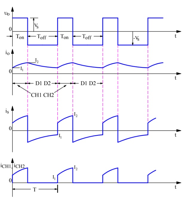
Thus, the average output voltage of Class-D chopper may either be positive or negative depending upon whether TON is more or TOFF.
Average output voltage Vo is given as below.
Vo = Vs [(TON – TOFF) / T]
where T = TON+TOFF
From the above formula, following points can be concluded and the same can be checked from quadrant operation of class-D chopper shown earlier in the figure:
- In case TON>TOFF i.e. duty cycle α>0.5, Vo is positive.
- In case TON<TOFF i.e. duty cycle α<0.5, Vo is negative.
- In case of TON = TOFF, α = 0 and hence, Vo = 0.
Now, refer the waveform of load current. It can be seen that; load current is always positive irrespective of CH1 & CH2 are ON or OFF. Thus, the average value of load current Io will always be positive.
Description.
The 200 HP DC motor is separately excited with a constant 150 V DC field voltage source. The armature voltage is provided by an IGBT buck-boost converter controlled by two PI regulators. The buck-boost converter is fed by a 630 V DC bus obtained by rectification of a 460 V AC 60 Hz voltage source. In order to limit the DC bus voltage during dynamic braking mode, a braking chopper has been added between the diode rectifier and the DC6 block.
The first regulator is a speed regulator, followed by a current regulator. The speed regulator outputs the armature current reference (in p.u.) used by the current controller in order to obtain the electromagnetic torque needed to reach the desired speed. The speed reference change rate follows acceleration and deceleration ramps in order to avoid sudden reference changes that could cause armature over-current and destabilize the system. The current regulator controls the armature current by computing the appropriate duty ratios of the 5 kHz pulses of the two IGBT devices (Pulse Width Modulation).For proper system behaviour, the two IGBT devices have opposite instantaneous pulse values.This generates the average armature voltage needed to obtain the desired armature current. In order to limit the amplitude of the current oscillations, a smoothing inductance is placed in series with the armature circuit.
Input
DC6-Two-Quadrant Chopper 200 HP DC Drive.

Output:- Simulink Reuslt


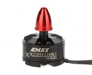
3. Explain in a brief about operation of BLDC motor.
What is a Brushless DC or BLDC Motor?
Brushless DC motors are common in industrial applications across the world. At the most basic level, there are brushed and brushless motors and there are DC and AC motors. Brushless DC motors, as you may imagine, do not contain brushes and use a DC current. A Brushless DC Motor, BLDC accomplishes commutation electronically using rotor position feedback to determine when to switch the current. The BLDC motor is electrically commutated by power switches instead of brushes.
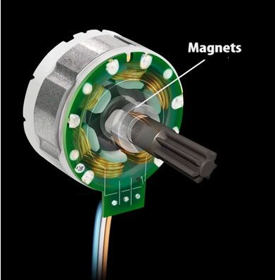
Brushless DC electric motors also known as electronically commutated motors (ECMs, EC motors). Primary efficiency is a most importent feature for BLDC motors. Because the rotor is the sole bearer of the magnets and it doesn't require any power. i.e. no connections, no commutator and no brushes. In place of these, the motor employs control circuitry. To detect where the rotor is at certain times, BLDC motors employ along with controllers, rotary encoders or a Hall sensor.

How a Brushless DC Motor Works
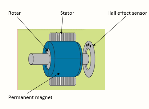
It often helps to explain how a brushed DC motor works first, as they were used for some time before brushless DC motors were available. A brushed DC motor has permanent magnets on the outside of its structure, with a spinning armature on the inside. The permanent magnets, which are stationary on the outside, are called the stator. The armature, which rotates and contains an electromagnet, is called the rotor. In a brushed DC motor, the rotor spins 180-degrees when an electric current is run to the armature. To go any further, the poles of the electromagnet must flip. The brushes, as the rotor spins, make contact with the stator, flipping the magnetic field and allowing the rotor to spin a full 360-degrees.
A brushless DC motor is essentially flipped inside out, eliminating the need for brushes to flip the electromagnetic field. In brushless DC motors, the permanent magnets are on the rotor, and the electromagnets are on the stator. A computer then charges the electromagnets in the stator to rotate the rotor a full 360-degrees.
Construction of Brushless DC motor
In this motor, the permanent magnets attach to the rotor. The current-carrying conductors or armature winding are located on the stator. They use electrical commutation to convert electrical energy into mechanical energy.

The main design difference between a brushed and brushless motors is the replacement of mechanical commutator with an electric switch circuit. A BLDC Motor is a type of synchronous motor in the sense that the magnetic field generated by the stator and the rotor revolve at the same frequency.
Brushless motor does not have any current carrying commutators.The field inside a brushless motor is switched through an amplifier which is triggered by the commutating device like an optical encoder.
The layout of a DC brushless motor can vary depending on whether it is in “Out runner” style or “Inrunner” style.
-
Outrunner – The field magnet is a drum rotor which rotates around the stator. This style is preferred for applications that require high torque and where high rpm isn’t a requirement.
-
In runner – The stator is a fixed drum in which the field magnet rotates. This motor is known for producing less torque than the out runner style, but is capable of spinning at very high rpm.

BLDC
Stator
There are three types of the BLDC motor:
- Single-phase
- Two-phase
- Three-phase.
Stator for each type has the same number of windings. The single-phase and three-phase motors are the most widely used. The simplified cross section of a single-phase and a three-phase BLDC motor is shown in figure below. The rotor has permanent magnets to form two magnetic pole pairs, and surrounds the stator, which has the windings.
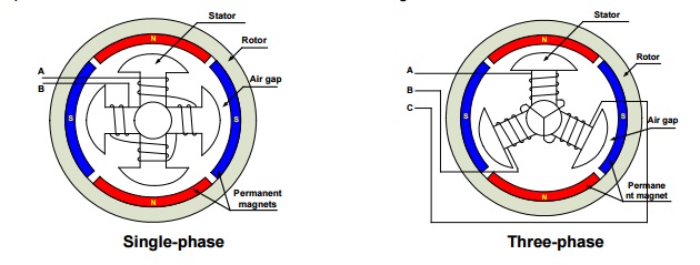
A single-phase motor has one stator winding wound either clockwise or counter-clockwise along each arm of the stator to produce four magnetic poles. A three phase BLDC motor has three windings. Each phase turns on sequentially to make the rotor revolve.
Rotor
A rotor consists of a shaft and a hub with permanent magnets arranged to form between two to eight pole pairs that alternate between north and south poles. Figure below shows cross sections of three kinds of magnets arrangements in a rotor.

Hall Sensors
Hall sensor provides the information to synchronize stator armature excitation with rotor position. Since the commutation of BLDC motor is controlled electronically, the stator windings should be energized in sequence in order to rotate the motor. Before energizing a particular stator winding, acknowledgment of rotor position is necessary. So the Hall Effect sensor embedded in stator senses the rotor position. Most BLDC motors incorporate three Hall sensors which are embedded into the stator. Each sensor generates Low and High signals whenever the rotor poles pass near to it. The exact commutation sequence to the stator winding can be determined based on the combination of these three sensor’s response.
Working Principle of Brushless DC Motor
BLDC motor works on the principle similar to that of a Brushed DC Motor. The Lorentz force law which states that whenever a current carrying conductor placed in a magnetic field it experiences a force. As a consequence of reaction force, the magnet will experience an equal and opposite force. In the BLDC motor, the current carrying conductor is stationary and the permanent magnet is moving.
When the stator coils get a supply from source, it becomes electromagnet and starts producing the uniform field in the air gap. Though the source of supply is DC, switching makes to generate an AC voltage waveform with trapezoidal shape. Due to the force of interaction between electromagnet stator and permanent magnet rotor, the rotor continues to rotate. With the switching of windings as High and Low signals, corresponding winding energized as North and South poles. The permanent magnet rotor with North and South poles align with stator poles which causes the motor to rotate.
Animation of BLDC Motor

- Less overall maintenance due to absence of brushes
- Reduced size with far superior thermal characteristics
- Higher speed range and lower electric noise generation.
- It has no mechanical commutator and associated problems
- High efficiency and high output power to size ratio due to the use of permanent magnet rotor
- High speed of operation even in loaded and unloaded conditions due to the absence of brushes that limits the speed
- Smaller motor geometry and lighter in weight than both brushed type DC and induction AC motors.
- Long life as no inspection and maintenance is required for commutator system
- Higher dynamic response due to low inertia and carrying windings in the stator
- Less electromagnetic interference
- Low noise due to absence of brushes
Limitations of Brushless DC motor.
- These motors are costly
- Electronic controller required control this motor is expensive
- Requires complex drive circuitry
- Need of additional sensors
Applications of Brushless DC motor.
Brushless DC motors (BLDC) use for a wide variety of application requirements such as varying loads, constant loads and positioning applications in the fields of industrial control, automotive, aviation, automation systems, health care equipments etc.
- Computer hard drives and DVD/CD players
- Electric vehicles, hybrid vehicles, and electric bicycles
- Industrial robots, CNC machine tools, and simple belt driven systems
- Washing machines, compressors and dryers
- Fans, pumps and blowers.
CONCLUSION:
All the above three study shows that difference between the H-bridge model and Four quadrant chopper (DC7) model. The advantages and applications of these two models are also explained in the above study. Each model has their individual specialties that may based on the application of the motor. In H-bridge the motor is controlled by changing the polarity which turns into opposite direction. In chopper model we need to interrupt one signal under control of another. The 2-quadrant chopper using simulink is also simulated and results are obtained according to our specified inputs. The brief about operation of BLDC motor and show the Animation of BLDC Motor.
Leave a comment
Thanks for choosing to leave a comment. Please keep in mind that all the comments are moderated as per our comment policy, and your email will not be published for privacy reasons. Please leave a personal & meaningful conversation.
Other comments...
Be the first to add a comment
Read more Projects by Pratik Mankar (13)
Week 1 Understanding Different Battery Chemistry
Pratik Mankar AIM To understand different Battery chemistry. OBJECTIVES 1] Prepare a table which includes materials & chemical reactions occurring at the anode and cathode of LCO, LMO, NCA, NMC, LFP and LTO type of lithium ion cells.Give your detailed explanation on it. 2]Compare the differences between…

24 Jan 2023 04:09 AM IST
Final Project: Electric Rickshaw modelling
Pratik Mankar AIM Design of an Electric Rickshaw using MATLAB Simulink (three wheel passenger vehicle). ABSTRACT In this project, we work to create the MATLAB model of the ELECTRIC RICKHAEW by doing a PM brushed type DC motor and a suitable Lithium-Ion battery for the motor. Before this, we will remember…
16 Jan 2023 04:36 PM IST
Project-1: Modelling an electric Car with Li-ion battery
Pratik Mankar AIM To Create a MATLAB model of an electric car in which we uses which uses lithium ion battery and suitable motor choosing a suitable blocks from the Powertrain block set and Implement the Vehicle Speed by using PI Controller and generate the accelerator and brake commands. OBJECTIVES To prepare the…
04 Jan 2023 04:18 AM IST
Project 1 (Mini Project on Vehicle Direction Detection
Pratik Mankar MBD Live Batch 2 Mini Project - Vehicle Direction Determination AIM To create the Vehicle Direction Determination model according to the given requirements. INTRODUCTION Identifying the direction of the vehicle is one of the important & diverse features in Autonomous driving…
30 Sep 2022 11:50 AM IST
Related Courses


Skill-Lync offers industry relevant advanced engineering courses for engineering students by partnering with industry experts.


Our Company

4th Floor, BLOCK-B, Velachery - Tambaram Main Rd, Ram Nagar South, Madipakkam, Chennai, Tamil Nadu 600042.

Top Individual Courses
Top PG Programs
Skill-Lync Plus
Trending Blogs
© 2025 Skill-Lync Inc. All Rights Reserved.